60
EN
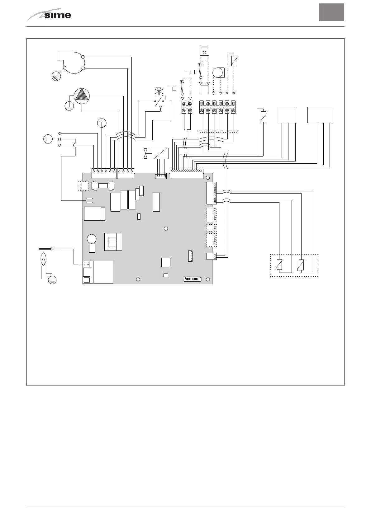
5.11 Wiring diagram
BROWN
BLUE
BLUE
BLUE
RED
RED
RED
GREEN
RED
ORANGE
GREEN
WHITE
RED
RED
BLUE
BROWN
BLACK
BLUE
BLACK
L
N
BLACK
BROWN
VD
SS
TPA
SAUX
TRA
EAR
EV
F
PI
V
FLM
CN6
CN5
CN3
CN17
CN4 CN1
CN15
CN14
CN13CN12
CN11
2
3
VCC
GND
IN
5V
GND
OUT
CN2
BLACK
BLACK
BLUE
BLUE
GREEN
GREEN
BLACK
BLACK
3 2 1456
SE
TA
TA2
CR
L
Line
N
Neutral
F
Fuse (3.15AT - 250V)
TRA
Ignition transformer
PI
System pump
V
Fan
EAR
Ignition / Detection electrode
EV
Gas solenoid valve
SS
Domestic hot water sensor
SM1-2
Dual sensor (thermal safety/delivery)
FLM
Flow meter
VD
Diverter valve
TPA
Pressure transducer
TA-TA2
Air thermostat
SE
External sensor
SAUX
Auxiliary sensor
CR
Remote control (instead of air thermo-
stat)
To connect the "Air Thermostat" or, alternatively the "Remote Control", remove the bridge
between terminals 5-6.
Fig. 14
m
CAUTION
Users must:
– Use an omnipolar cut-off switch, disconnect switch
in compliance with EN Standards
which ensures com-
plete cut-off in overvoltage category III conditions (i.e.
where ther
e is at least 3 mm between the open con-
tacts)
.
– Respect the connections L (Live) - N (Neutral).
– Ensure that the special power cable is only replaced
with a cable ordered as a spare part and connected
by professionally qualified personnel.
m
CAUTION
Users must:
– Connect the earth wire to an effective earthing sys-
tem.
The manufacturer is not responsible for any dam-
age caused by failure to earth the appliance or failure
to observ
e the information provided in the wiring dia-
grams
.
d
IT IS FORBIDDEN
To use water pipes for earthing the appliance.