66
EN
6.11.1 Coaxial duct (Ø 60/100mm and Ø 80/125mm)
Coaxial accessories
Description
Code
Ø 60/100
mm
Ø 80/125
mm
Coaxial duct kit 8084813 8084830
Extension W. 1000 mm 8096103 8096130
Extension W. 500 mm 8096102 -
Vertical extension W. 200 mm with
smoke analysis take-off point
8086908 -
Adapter for Ø 80/125 mm - 8093120
Additional 90° curve 8095801 8095820
Additional 45° curve 8095900 8095920
Tile with joint 8091300 8091300
Roof outlet terminal W. 1284 mm 8091200 8091200
Vertical condensation recovery W. 200
mm
8092803 8092803
Load loss - Equivalent lengths
Model
Leq (linear metres)
Ø 60/100
mm
Ø 80/125
mm
90° curve 1 1
45° curve 0,5 0,8
Minimum-Maximum Lengths
Model
Duct Length Ø 60/100 Duct Length Ø 80/125
W Horizontal
(m)
H Vertical (m)
W Horizontal
(m)
H Vertical (m)
Min.
Max.
Min.
Max.
Min.
Max.
Min.
Max.
Brava Slim
25 BF
- 3,5 1,3 (*) 5 3,5 6 4 7
Brava Slim
30 BF
- 3,0 1,3 (*) 5 3 6 4 7
Brava Slim
40 BF
- 3,0 1,3 (*) 5 3 6 4 7
m
CAUTION
(*) Vertical condensate recovery MUST be introduced
for vertical ducts (Type C32) or vertical sections of the
duct (Type C42) longer than 1.3m.
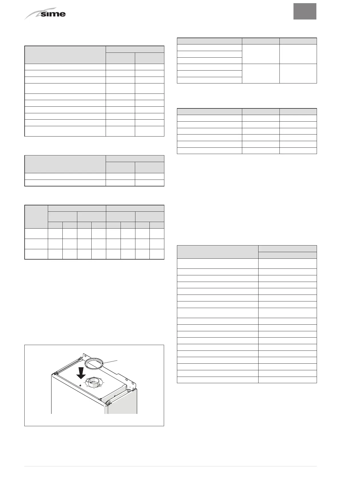
Diaphragms for coaxial ducts
Boilers leave the factory equipped with a diaphragm (1) with the
following characteristics:
–
Brava Slim 25 BF
: diaphragm Ø 79 mm
–
Brava Slim 30 BF
: diaphragm Ø 81 mm
–
Brava Slim 40 BF
: diaphragm Ø 87,5 mm.
1
Fig. 22
When the outlets are
Type C12
or
C42
the diaphragm is to be re-
moved or kept following the indications below:
Model Diaphragm for duct L
Brava Slim 25 BF
YES
(leave mounted)
< 1 m
Brava Slim 30 BF
Brava Slim 40 BF
Brava Slim 25 BF
NO
(remove it)
> 1 m
Brava Slim 30 BF
Brava Slim 40 BF
When the outlet is
Type C32
(vertically straight without any curves),
the presence of the diaphragm modifies the maximum length of
the duct as shown below:
Model Diaphragm Max L (m)
Brava Slim 25 BF
YES 2,5
Brava Slim 25 BF
NO 5
Brava Slim 30 BF
YES 2,5
Brava Slim 30 BF
NO 5
Brava Slim 40 BF
YES 2,5
Brava Slim 40 BF
NO 5
6.11.2 Separate ducts (Ø 80mm)
Constructing outlets for separate ducts indicates the use of the
"air-flue split pipe system". This is to be ordered separately from
the boiler and when connected to the other accessories, from
those listed in the table below, completes the smoke-outlet/
combustion air inlet assembly.
The total maximum length, obtained by adding the length of the
outlet and inlet pipes, is determined by the load loss of the indi
-
vidual accessories and must not be greater than 9 mm H
2
O for
Brava Slim 25 BF
, 9.5 mm H
2
O for
Brava Slim 30 BF
and 15 mm
H
2
O for
Brava Slim 40 BF
.
Separate accessories
Description
Code
Diameter Ø 80 (mm)
Air-flue split pipe system (with take-off
point) + Diaphragm
8093020
90° curve M-F (6 pieces) 8077410
90° curve M-F (with take-off point) 8077407
90° curve M-F (insulated) 8077408
Extension W. 1000 mm (6 pieces) 8077309
Extension W. 1000 mm (insulated) 8077306
Extension W. 500 mm (6 pieces) 8077308
Extension W. 135 mm (with take-off
point)
8077304
Wall outlet terminal 8089501
Internal and external ring nut kit 8091500
Inlet terminal 8089500
45° curve M-F (6 pieces) 8077411
Condensate recovery W. 135 mm 8092800
Manifold 8091400
Tile with joint 8091300
Roof outlet terminal W. 1390 mm 8091201
Condensate recovery Tee 8093300
Inlet/outlet fitting Ø 80/125 mm 8091401