ched fittings (excluding the inlet/outlet
stub pipe) and should not be greater than
7.00 mm H
2
O.
To calculate the load loss of the individual fit-
tings attached see Table 2.
2.10 ELECTRICAL
CONNECTION
The boiler is supplied with an electric cable.
Should this require replacement, it must be
purchased exclusively from SIME.
The electric power supply to the boiler must
be 230V-50Hz single-phase through a
fused main switch, with at least 3 mm spa-
cing between contacts.
NOTE:
Device must be connected to an efficient
earthing system.
SIME declines all responsibility for injury
or damage to persons, animals or things,
resulting from the failure to provide for
proper earthing of the appliance.
2.10.1 Electric
switchboard (fig. 16)
To gain access to the electric switchboard
turn off the power supply, remove the front
panel and the two screws holding the con-
trol panel to the sides (see point 4.7).
The panel will tilt forward at a sufficient angle
to allow access to the components.
To remove the protection (6), unscrew the
fixing screws and use a screwdriver to relea-
se the upper tabs and free it from the con-
trol panel.
2.10.2 Room stat
connection (fig. 16)
To gain access to connector “TA”, remove
the control panel cover (7) and connect the
room stat to the terminals 10-11 after
having removed the jumper.
The thermostat or timer-thermostat,
recommended for better room tempe-
rature control, must be class II as spe-
cified by standard EN 60730.1 (clean
contact).
78
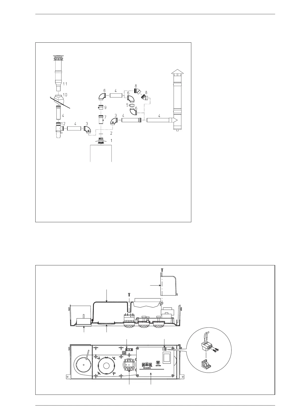
Fig. 15
KEY
1 Inlet/outlet terminal
2 Sectors diaphragm
3 90° elbow MF with point
cod. 8077407
4a Extension L. 1000 (6 pz.) cod. 8077309
4b Isolated extension L. 1000
cod. 8077306
4c Extension L. 500 (6 pz.) cod. 8077308
5 Locking junction (5 pz.) cod. 8092700
6 90° elbow MF (6 pz.) cod. 8077410
7 Extension L. 135 with point (6 pz.)
cod. 8077311
8 45° elbow MF cod. 8077406
9 Condensation outlet L. 135
cod. 8092800
10 Tile with articulated joint
cod. 8091300
11 Roof outlet terminal L. 1390
cod. 8091201
12 Tee condensation outlet
cod. 8093300
KEY
1 Thermomanometer
2 Timer-programmer housing
3 Rotary switch
4 Electronic board
5 Earth faston
6 Instrument protection
7 Room stat cover
8 Room stat connector (TA)
Fig. 16