4.5 GAS CONVERSION
A kit is supplied complete with the necessary
change-over materials for operation with
butane gas (G30) or propane gas (G31).
Operate in the following manner for changing
over from one gas to another (fig. 28):
– Close the gas cock.
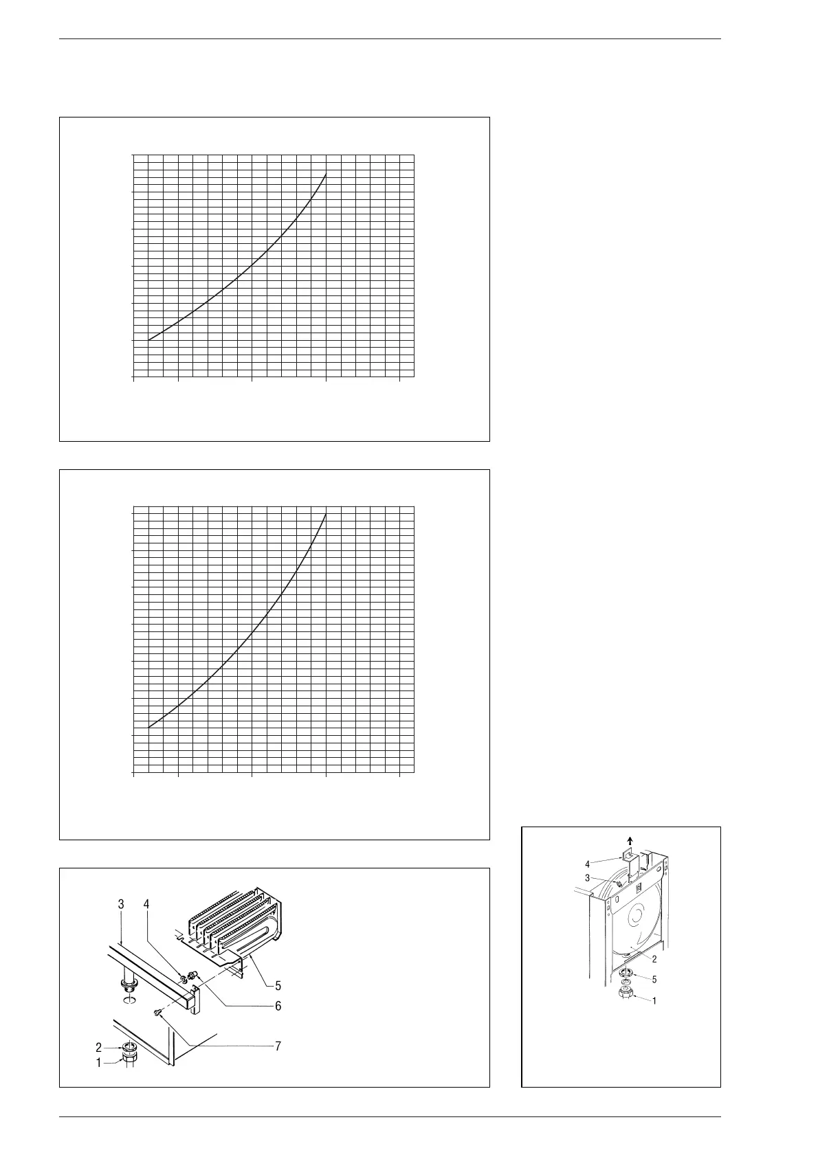
– Slide out the burner unit.
–
Replace the main nozzles (6) supplied in a
kit, inserting the copper washer (4). Use
a ø 7 spanner to perform this operation.
–
Remove the “METANO/GPL” connector
link on the card and set it on “GPL”(4
fig. 19).
– To set the values of maximum and mini-
mum gas pressure, follow the instruc-
tions given in section 4.3.
When the working pressures have
been adjusted, reseal the regulators.
– The gas feed pressure must, under no
circumstances, exceed 50 mbar.
– After have ultimated the conversion of
the boiler, please stick onto the casing
panel the plate showing the relevant fee-
ding gas which is included into the kit.
NOTE: After assembling all the gas con-
nections, a test for gas tightness must be
carried out using soapy water or special
products. Do not use naked flames.
The conversion to different gas must be
carried out exclusively by authorized tech-
nical personnel.
4.6 DISASSEMBLY OF
EXPANSION VESSEL
To disassemble the expansion vessel, pro-
ceed as follows (fig. 29):
– Make sure that the water has been emp-
tied out of the boiler.
– Unscrew the connection the expansion
vessel and the screws that release it
from its bracket.
Before refilling the system make sure that
the expansion vessel is preloaded at a pres-
sure of 0.8 to 1 bar.
85