28
Load loss accessory Ø 80 mm
Description Code
Load loss (mm H
2
O)
UNIQA REVOLUTION
Inlet
Outlet
90° curve MF 8077410 2,3 2,5
45° curve MF 8077411 2,0 2,0
Horizontal extension W. 1000
mm
8077309 1,0 1,3
Vertical extension W. 1000 mm 8077309 1,0 1,3
Wall terminal
8089550/51
1,1 3,6
Condensate recovery Tee 8093300 - 5,8
Roof outlet terminal (*) 8091200 1,15 1,0
(*) The losses of the roof outlet terminal at inlet include the
manifold code 8091400.
m
CAUTION
The total maximum length is obtained by adding the
length of the inlet and outlet pipes. The total load loss
is determined by the sum of the load losses of the
single accessories that make up the piping. It should
not exceed 21.5 mmH
2
O.
NOTE:
for the boiler to operate correctly it is necessary that a
minimum distance of 0.50 m of the duct is respected with a 90°
inlet curve.
Example: calculation of the load loss of a
UNIQA REVOLUTION
boiler.
Accessories Ø 80
mm
Code
Quantity
Load loss (mm H
2
O)
Inlet Outlet Total
Extension W. 1000
mm (horizontal)
8077309 2 2 x 1.0 - 2,0
Extension W. 1000
mm (horizontal)
8077309 2 - 2 x 1,3 2,6
90° curve 8077410 1 1 x 2,3 - 2,3
90° curve 8077410 1 - 1 x 2,5 2,5
Wall terminal 8089550/51 1 1,1 3,6 4,7
TOTAL 14,1
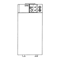
Installation is permitted as the total load loss (14,1 mmH
2
O) for
the required accessories is less than 21,0 mmH
2
O. With this
total load loss, fold sections 1 to 9 (inclusive) on the flue gas
outlet diaphragm (4).
4
Fig. 25
No. of sections to be
removed
Total load loss (mm H
2
O)
UNIQA REVOLUTION
1 ÷ 5 0 ÷ 5,0
1 ÷ 6 5,1 ÷ 7,5
1 ÷ 7 7,6 ÷ 10,0
1 ÷ 8 10,1 ÷ 15,0
1 ÷ 9 15,1 ÷ 20,0
1 ÷ 10 20,1 ÷
21,0
(*)
(*) Maximum load loss permitted.