46
–
open one or more than one hot water tap
– press the button
>
to make the boiler operate at maximum
power
"Hi"
and check that the gas pressure values on the
pressure gauges correspond to those indicated in the table
below
– read the combustion parameters (CO
2
particularly) and the
combustion performance
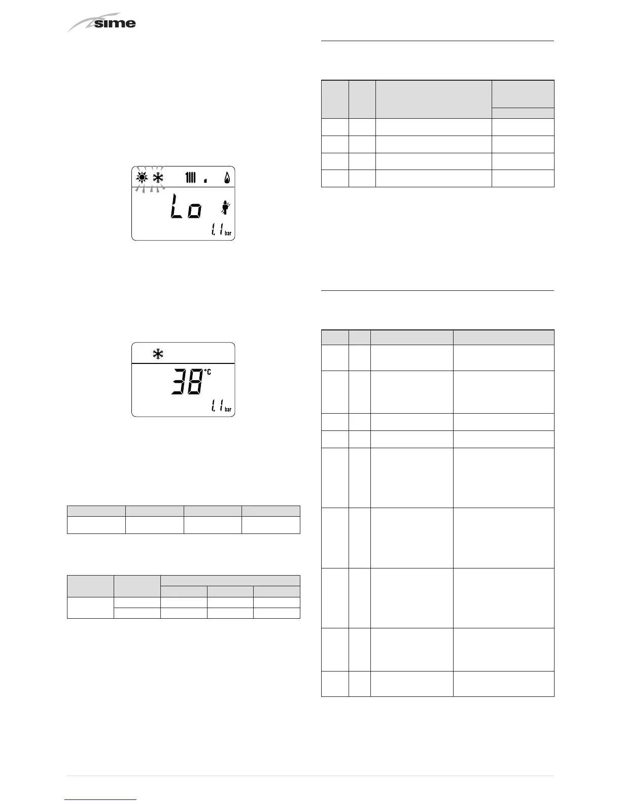
– press the button
<
to make the boiler operate at minimum
power "Lo" and check that the gas pressure values on the
pressure gauges correspond to those indicated in the table
below. The message “Lo” will appear on the display together
with the flashing symbols
l
and
n
– press the button
>
once again to make the boiler operate at
maximum power. If the gas pressure values are correct it is
possible to determine the combustion data and take a reading
of the combustion efficiency as provided for by legislation in
force
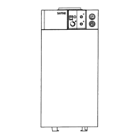
– press the button
y
to exit the "Chimney sweeper
Procedure”. The boiler water delivery temperature will
appear on the display
– close the taps opened previously and check that the appliance
shuts down
– disconnect the pressure gauges, carefully close the pressure
points (6) and (7), put the control panel back to the original
position and refit the front panel (2).
Gas supply pressure
Type of gas G20 G30 G31
Pressure
(mbar)
20 29 37
Installations with SPLIT and CONCENTRIC flue gas outlet pipe
systems
Model
Heat
Output
Pressure at nozzles (mbar)
G20 G30 G31
UNIQA
REVOLUTION
Max 13,3 - 13,8 27,2 - 27,7 35,2 - 35,7
min 2,9 - 3,2 5,0 - 5,4 6,1 - 6,5
8.6 Unscheduled maintenance
If replacing the
electronic board
, the user MUST set the
parameters as indicated in the table.
Type No. Description
Setting
for
UNIQA
REVOLUTION
-
PAR 01
Index showing boiler power in kW
0 = 25
0
PAR 02
Hydraulic configuration
5 = Low NOx ErP
5
PAR 03
Gas Type Configuration
0 = G20; 1 = LPG
0 or 1
PAR 04
Combustion configuration
3 = Low NOx ErP APS
3
To enter "Parameter setting and display"refer to the indications
provided in the specific section.
Once the parameters in the table have been set, you must carry
out the "Automatic calibration procedure".
If the
gas valve
and/or the
ignition/detection electrode
and/or the
fan
are replaced, the user must still carry out the entire phase
of "Automatic calibration procedure" described in the specific
section.
8.7 Malfunction codes and possible solutions
LIST OF MALFUNCTION/FAULT ALARMS
Type No. Fault Solution
ALL 02
Low water pressure in
system
- Restore pressure
- Check for any leaks in the
system
ALL 03
High water pressure in
system
- Empty the system via the
drain valve on the hydraulic
assembly and bring the
pressure to approximately
1.2 bar
ALL 04
Domestic hot water
sensor fault
- Check connections
- Replace the sensor
ALL 05 Delivery sensor fault
- Check connections
- Replace the sensor
ALL 06 No flame detection
- Check the integrity of the
electrode and check that it
is not grounded
- Check gas availability and
pressure
- Check the integrity of the
gas valve and the card
ALL 07
Safety thermostat
intervention
- Check the delivery sensor
connections
- Deaerate the system
- Check the bleed valve
- Replace the delivery sensor
- Check that the pump
impeller is not blocked
ALL 08
Fault in the flame
detection circuit
- Check the integrity of the
electrode and check that it
is not grounded
- Check gas availability and
pressure
- Check the integrity of the
gas valve and the card
ALL 09
No water circulating in
the system
- Check the rotation of the
pump rotor
- Check the electrical
connections
- Replace the pump
ALL 10 Air inlet probe error
- Check the probe
- Check the electrical
connection