29
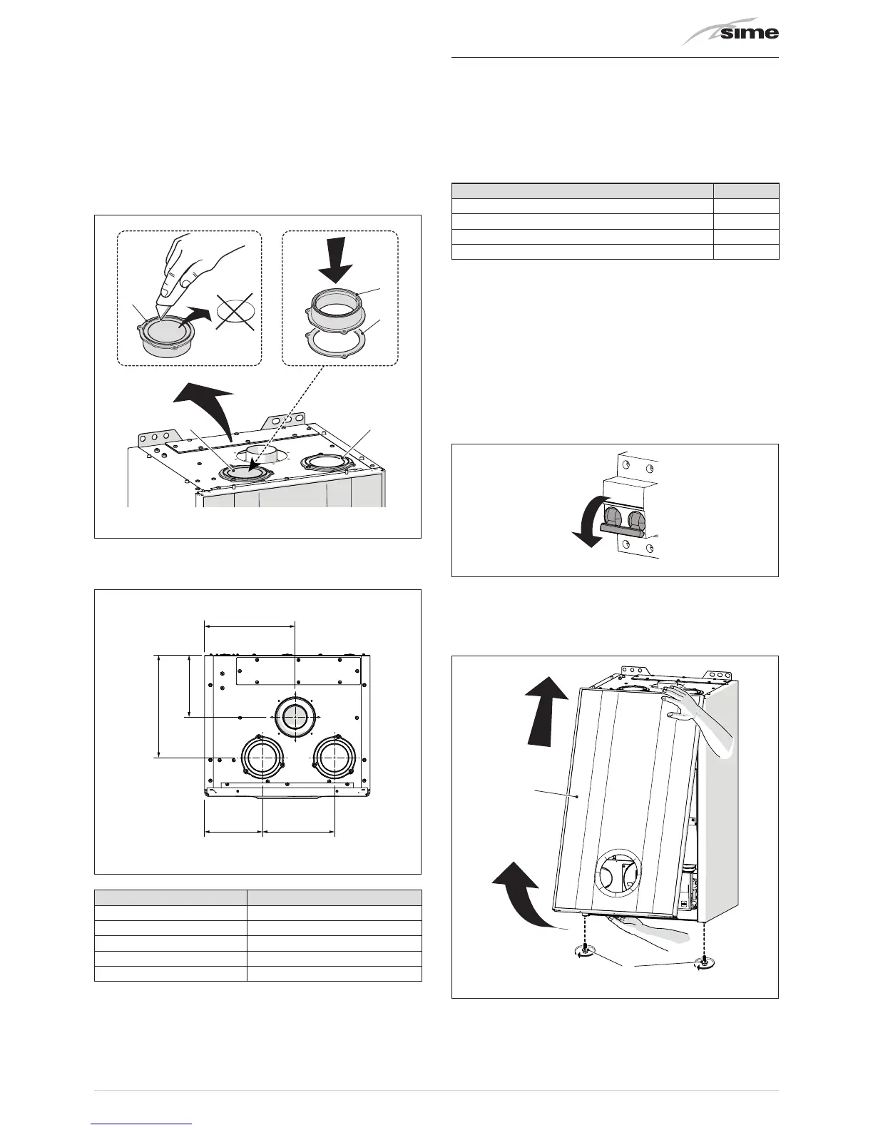
Combustion air inlet
The combustion air inlet, with separate ducts, is assembled as
follows:
– remove the air outlet cap (5); choose your preferred outlet
– cut the bottom of the cap (5) using a suitable tool (a)
– turn over the cap (5) as shown (b) and refit it on the air outlet,
inserting the new seal (6) provided in the kit
– fix everything in place with the screws removed previously.
The overturned cap (5) is now the attachment for the first
component on the air inlet duct
5
ba
6
5
5 5
Fig. 26
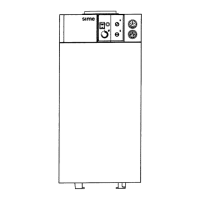
Smoke outlet and combustion air inlet fittings
Fig. 27
Description
UNIQA REVOLUTION
A (mm) 248
B (mm) 140
C (mm) 175
D (mm) 180
E (mm) 220
6.12 Electrical connections
The boiler is equipped with a ready wired power cable which is
to be connected to a 230V~50 Hz network.
If this cable needs to be replaced, an original spare must be
requested from
Sime
.
Therefore only the connections of the original components
as shown in the table are needed. These are to be ordered
separately from the boiler.
DESCRIPTION CODE
External sensor kit (ß=3435, NTC 10KOhm at 25°C) 8094101
Power cable (dedicated) 6329400
Remote control HOME (open therm) 8092280
Remote control HOME PLUS (open therm) 8092281
m
CAUTION
The maintenance interventions described must ONLY
be carried out the professionally qualified personnel.
a
WARNING
Before carrying out any interventions described:
– set the main system switch to "OFF"
– close the gas valve
– make sure that no hot parts inside the appliance are
touched.
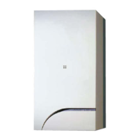
Fig. 28
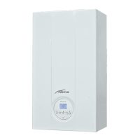
To facilitate introduction of the connection wires of the optional
components into the boiler:
– remove the screws (1), pull the front panel (2) forwards and
release it from the top by lifting it
1
2
Fig. 29