3.2.1. Tx/Rx Connections
The Tx antenna connection on the SDB680 Base Station is provided with a 50 Ω female
N-type socket, while for the Rx antenna connection a 50 Ω female Bayonet Neill-
Concelman (BNC) socket is used.
The Tx antenna cable connections must be made with 50 Ω N-type on flexible tails. The
Voltage Standing Wave Ratio (VSWR) of the Tx and Rx connections should be tested
prior to use by using of a suitable test set, e.g. an Anritsu/Wiltron S331A. A VSWR of
1.5:1 or better at the relevant Tx and Rx frequencies should be ensured.
Mating connectors should be galvanically compatible with nickel outer and gold centre
pin to minimise passive intermodulation.
A minimum of 85 dB transmit-receive isolation should be provided by the antenna
system and associated filters.
It is recommended that a good quality flexible co-axial cable is used, e.g. with double-
screening braid and multi-strand copper inner.
CAUTION
The Antenna System should be protected against lightning by means of an
earthing system and surge protection device. Do not connect Antenna
Lightning conductors to the base station or Mains Earth.
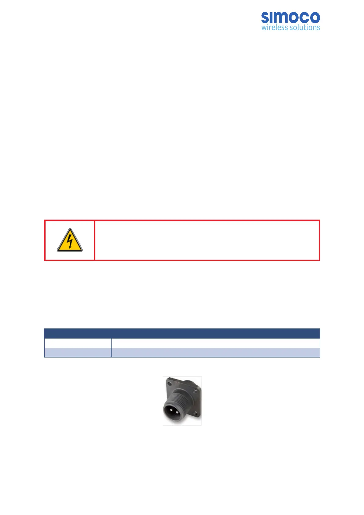
3.2.2. Power Connection
The DC power input is via a 2-pin IP67 DC plug connector. The two pins are wired to
suit the voltage range shown in Table 2.
Pin Description
A +14.0 V
B Ground
Table 2: DC Power Connector Pin-outs.
Figure 2: 2-pin IP67 DC Power Connector.
Doc Number: TNM-I-E-0046 ISSUE 1.2 Page 30