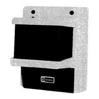
2098-9816 Remote Indicator Plate
If a 2098-9816 Remote Indicator Plate is used, the following information applies to the 2098-9816:
.
Locate the 2098-9816 Remote Indicator Plate no further than 50 feet from the 2098-9207 Receiver.
.
Connect wiring to the 2098-9816 Receiver using the supplied 6-wire plug.
.
For remote LEDs, connect the red, yellow, and green wires to red (alarm), yellow (trouble), and green
(normal) LEDs, respectively.
.
For a remote test, turn key switch to test position until alarm.
.
For reference voltage measurements, connect a DC voltmeter to test point jacks marked VOLTS OUT
(+I & (4.
.-
NOTE:
For mounting information on the 2098-9816 Remote Indicator Plate, see ACCESSORY MOUNTING on
page 17.
2099-9207 Remote Indicator Plate Wiring
FIGURE 7
8
Technical Manuals Online! - http://www.tech-man.com

 Loading...