CPU (see Figure 1)
TEST POINT 1
+5 Volts
TEST POINT 2
+ 24 Volts
TEST POINT 3
24 Volt Common
MICROPROCESSOR
U23
Terminal Blocks
TBl
8 Initiating Device Circuits (monitor zones) (TBl-1 thru TBl-
16)
Style B (formerly Class B) (f.w.d. 841-669, pg. 6) Terminate
with 3.3k E.O.L. resistor
Style D (formerly Class A) (f.w.d. 841-669, pg. 8)
If coded manual station exists on zone 1, cut JW-11 (f.w.d.
841-669, pg. 21)
Water/sprinkler supervisory wiring (f.w.d. 841-669, pg. 21)
Remove the appropriate jumper if the zone is connected to a:
Zone Disconnect Module
Zone Suppression Module
Combination Zone Disconnect/Suppression Module
TB2
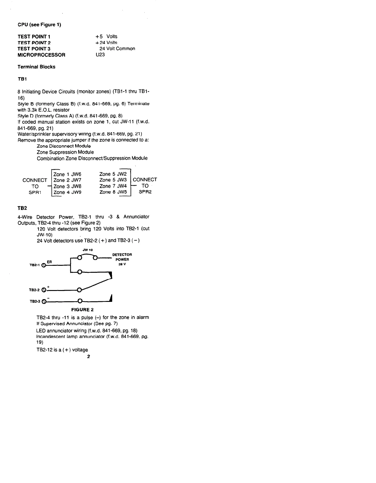
4-Wire Detector Power, TB2-I thru -3 & Annunciator
Outputs, TB2-4 thru -12 (see Figure 2)
120 Volt detectors bring 120 Volts into TB2-1 (Cut
JW-10)
24 Volt detectors use TB2-2 ( + ) and TB2-3 ( -)
JW 10
ER
- POWER
TBi-1
3
DETECTOR
28 v
TBZ-2 (9+
TB2-3 -
FIGURE 2
TB2-4 thru -11 is a pulse (-) for the zone in alarm
If Supervised Annunciator (See pg. 7)
LED annunciator wiring (f.w.d. 841-669, pg. 18)
Incandescent lamp annunciator (f.w.d. 841-669, pg.
19)
TB2-12 is a ( + ) voltage
2
Technical Manuals Online! - http://www.tech-man.com