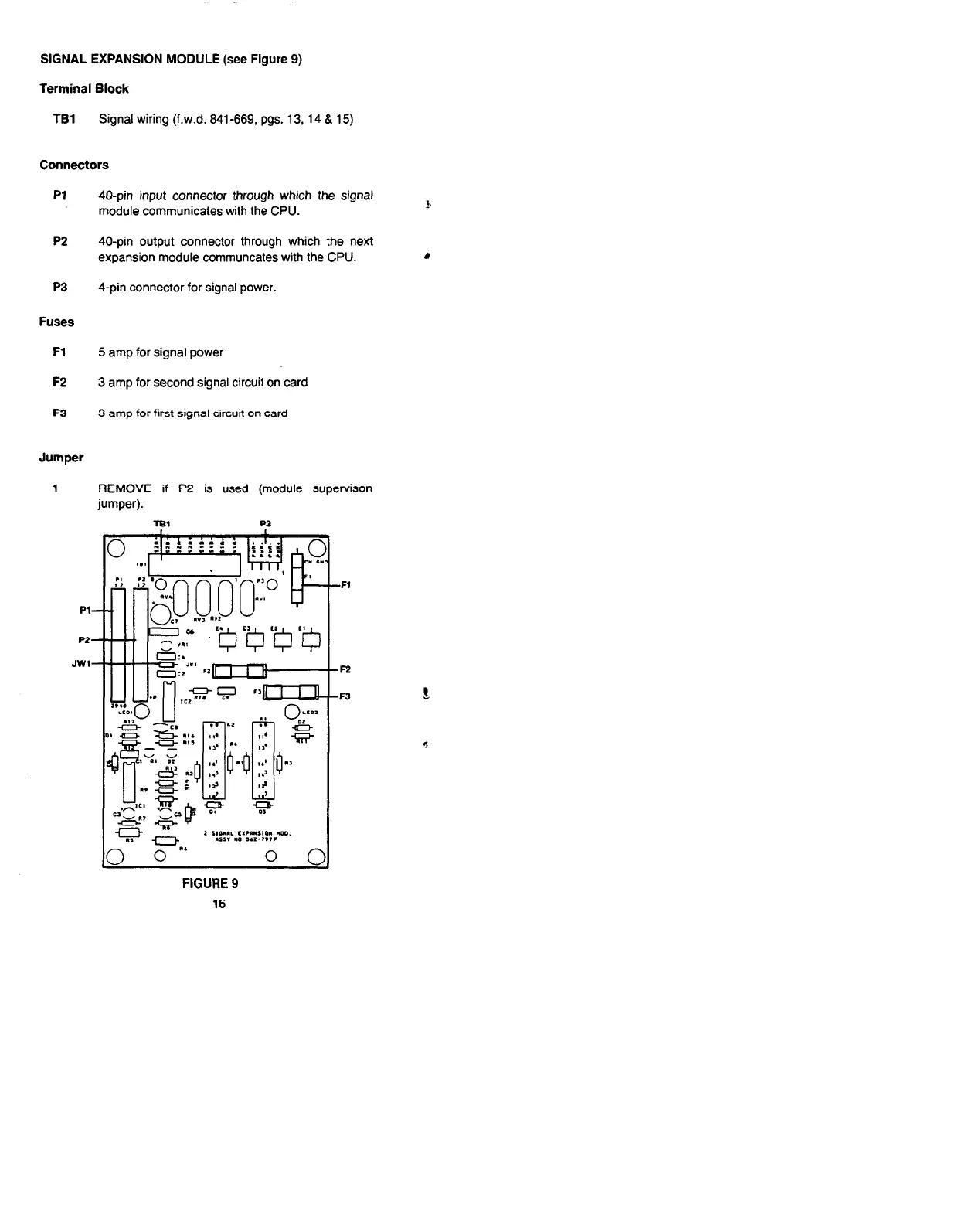
SIGNAL EXPANSION MODULE (see Figure 9)
Terminal Block
TBl Signal wiring (f.w.d. 841-669, pgs. 13, 14 & 15)
Connectors
Pl 40-pin input connector through which the signal
module communicates with the CPU.
P2 40-pin output connector through which the next
expansion module communcates with the CPU.
P3
4-pin connector for signal power.
Fuses
Fl
5 amp for signal power
F2 3 amp for second signal circuit on card
F3
3 amp for first signal circuit on card
Jumper
1
REMOVE if P2 is used (module supervison
5
JWl
“, -“, 2 ‘::::‘.:‘:::f;::,*““.
‘0 0
0 c
FIGURE 9
16
-Fl
-F2
-F3
Technical Manuals Online! - http://www.tech-man.com