CPU (cont’d)
See Figure 4
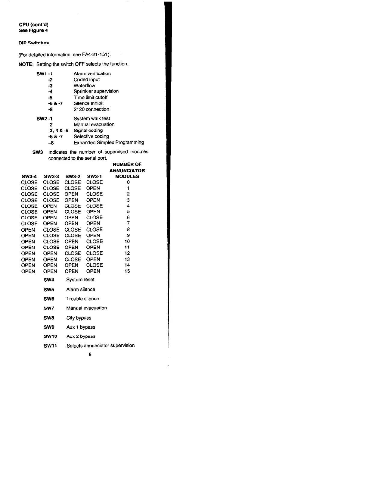
DIP Switches
(For detailed information, see FA4-21-151).
NOTE: Setting the switch OFF selects the function.
SW1 -1 Alarm verification
-2
Coded input
-3 Waterflow
-4
Sprinkler supervision
-5
Time limit cutoff
-6 & -7
Silence inhibit
-8 2120 connection
SW2 -1
System walk test
-2 Manual evacuation
-3,-4 & -5
Signal coding
-6 & -7 Selective coding
-8
Expanded Simplex Programming
SW3 Indicates the number of supervised modules
connected to the serial port.
NUMBER OF
ANNUNCIATOR
SW3-4 SW3-3 SW3-2 SW3-1 MODULES
C&OSE CLOSE CLOSE CLOSE
0
CLOSE CLOSE CLOSE OPEN
1
CLOSE CLOSE OPEN CLOSE
2
CLOSE CLOSE OPEN OPEN
3
CLOSE OPEN CLOSE CLOSE
4
CLOSE OPEN
CLOSE OPEN 5
CLOSE OPEN OPEN CLOSE
6
CLOSE OPEN OPEN OPEN
7
OPEN CLOSE CLOSE CLOSE
8
OPEN
CLOSE CLOSE OPEN 9
-OPEN
CLOSE OPEN
CLOSE
10
OPEN CLOSE OPEN OPEN
11
OPEN OPEN CLOSE CLOSE
12
OPEN OPEN CLOSE OPEN 13
OPEN
OPEN OPEN
CLOSE
14
OPEN
OPEN OPEN OPEN 15
SW4
System reset
SW5
Alarm silence
SW6
Trouble silence
SW7
Manual evacuation
SW8
City bypass
SW9
Aux 1 bypass
SW10 Aux 2 bypass
SW1 1 Selects annunciator supervision
6
Technical Manuals Online! - http://www.tech-man.com