3-2
Description
Weight
(See Note 5)
Height Width
Rough Opening
(See Note 2)
Size Box Door Box Door Box Door Height Width
4004 6.5 lb 3.5 lb 16-1/8 in. 17 in. 14-1/2 in. 16-1/8 in. 16-1/8 in. 14-1/2 in.
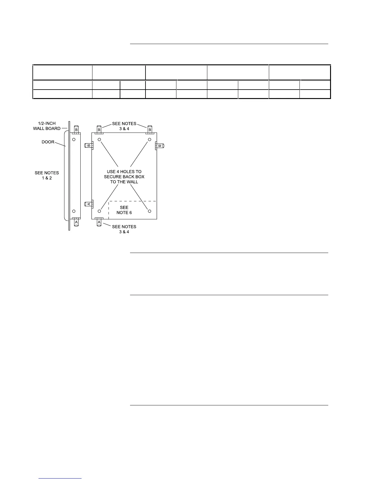
CAUTION: Enclosure must be level and plumb when installing the back box.
Figure 2. Back Box Mounting
See the interconnect wiring diagram in Figure 3 for basic information on 4004
system wiring. For detailed wiring information, including circuit loading
capacities, distance specifications, and wire size, refer to Figure 1 and the
841-992 Field Wiring Diagram (supplied with the FACP).
The Base 4004 System [565-691] consists of:
A System Board with 2-IDCs and 2-NACs - Each IDC on the system board is
capable of supporting up to 30 compatible two-wire detectors. Alarm
verification is supported, with current-limited alarms being verified. Contact
closure results in an immediate alarm. Support for Style D (Class A) IDCs is via
an expansion module. A zone disconnect switch is provided for each IDC.
When restoring a zone to the operative state, activation of notification circuits is
inhibited for 15-seconds. The system sounder and display is not delayed if the
restored zone is in the alarm state. This allows the operator or service technician
to restore the IDC to the disabled state without a general alarm. This operation
is called “Abort Enable” of the IDC. The selectable IDC types allow the user to
define each zone as Fire Monitor, Alarm Verification, Fire/Supervisory, Trouble,
and Style C (See the Programming Instructions section of this chapter).
Continued on next page
Back Box (Continued)
Wiring
System Modules
Notes:
1. The box can be mounted semi-flush with the surface
of the wall (the cabinet protrudes approximately 3/8”).
2. Dimensions shown are typical for all surface and
semi-flush installations. Use rough opening
dimensions preparing semi-flush installation.
3. “A” conduit denotes non-power limited wiring only.
“B” conduit denotes power-limited wiring only.
4. When providing additional conduit entrances to the
box use a suitable knockout punch to provide
separate entrances for power-limited and non-power
limited wiring at the opposite ends of the box. Check
system label on door for power-limited information.
5. Box weight in pounds (without batteries).
6. This space must be kept free of wiring for battery
installation.