4-3
The “ACK” key is also used to perform a lamp test on the system LEDs and
displays. When the “ACK” key is pressed for five seconds, the red and
yellow, seven-segment displays (all segments), System tone-alert and Power
On, Alarm Silenced, and Supervisory LEDs turn ON and remain ON until
the “ACK” key is released.
8. Alarm Silence Key - The “ALARM SILENCE” key de-energizes NACs
configured as “On Until Silence.” The “ALARM SILENCED” LED turns
ON and remains ON until all alarms are cleared.
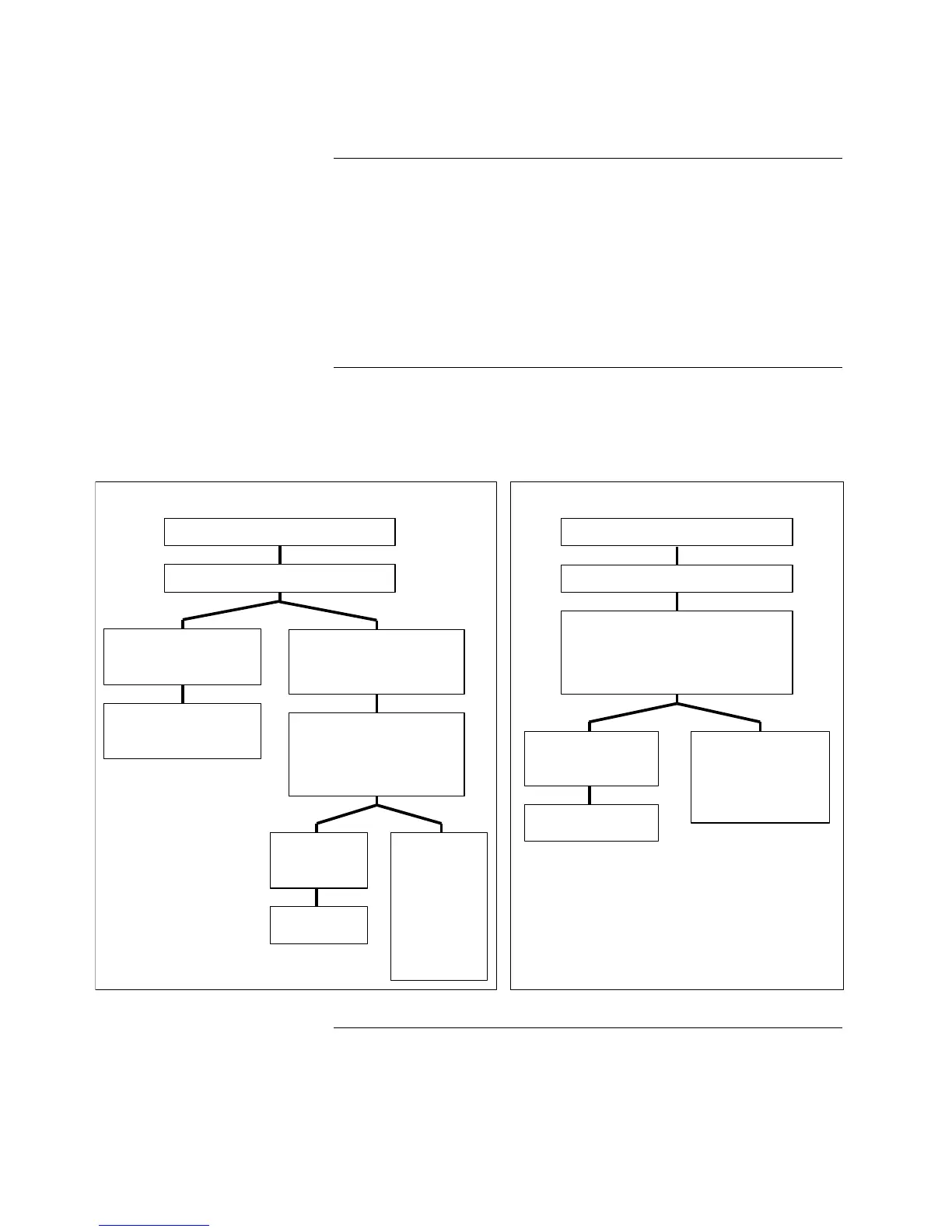
Follow the flow chart below to initialize the 4004 FACP.
IMPORTANT: Notify appropriate personnel (building occupants, fire
department and/or monitoring facility, etc.) of power-up.
Operator Key Definitions
(Continued)
System Initialization
(Power-Up)
NORMAL POWER-UP CONDITIONS POWER-UP TROUBLE CONDITIONS
Apply system power to the 4004 panel.
The panel displays and indicators appear.
The tone alert sounds for one
second and the user interface
panel “AC POW ER” LED is ON.
The tone alert sounds continuously and
pressing the “ACK” key indicates a
system Supervisory, Trouble, or Alarm
on the red or yellow displays.
Program the 4004 for your desired
system configuration (See Chapter
2 – “Program m ing Instructions”).
If, a fte r c h e ck in g
c irc u its, th e S y s te m
appears O K.
If the system still
indicates conditions
on the red or yellow
d is p la ys a fte r fie ld
wiring checks,
contact your local
Simplex Branch
O ffice (lis te d in th e
Yellow Pages under
Fire Alarm ).
Apply system power to the 4004 panel.
Fuses m ay have opened or a circuit breaker m ay
have tripped.
Make sure power is removed from the panel and
appropriate circuit is disconnected from the
panel and when checking the system.
If, a fte r c h e ckin g fu se s and/or
circuits, the System appears
OK.
If a fuse continues to open or
circuit breaker continues to
trip , co n ta ct y o u r lo ca l
S im p le x B ra n c h O ffice (liste d
in the Yellow Pages under
Fire Alarm ).
Check Field W iring Diagram 841-992.
Make sure that power is removed
from the panel and the appropriate
circuit is disconnected from the
panel when checking the circuit.
The panel displays and indicators DO NOT appear.
Reapply power to
the System .
System .