3-7
CCDACT Module [565-626] - The DACT Module uses the same CPU card
connector as the City Connect Module, meaning a system may have either a
DACT Module or
a City Connect Module. A DACT trouble output will cause a
4004 system trouble, and is indicated on the seven segment display as a
"City/DACT Trouble" ("C"). Mounting conforms to Power Limited
requirements. The auxiliary Alarm output is on-until-reset. The trouble output
is active until the trouble condition is cleared. The Supervisory output is active
until the condition is cleared for all zones. The AC Fail signal delay is
programmable on the DACT to delay reporting this condition.
The following selections are made jumper settable – see Figure 1 for jumper
locations:
On Until Silence/Reset operation for each NAC.
1. Locate System Board jumpers P2 = NAC 1, P3 = NAC 2.
2. Jump P2-1 to P2-2 and P3-1 to P3-2 for “On Until Reset” operation.
3. Jump P2-2 to P2-3 and P3-2 to P3-3 for “On Until Silenced” operation.
This must be selected for coded operations.
City Circuit configuration for optional City Connect module.
1. To configure City Circuits 1 and 2 as Local Energy or Remote Station,
locate the City Connect module jumpers P2 - P5. Jump P2 - P5 as follows:
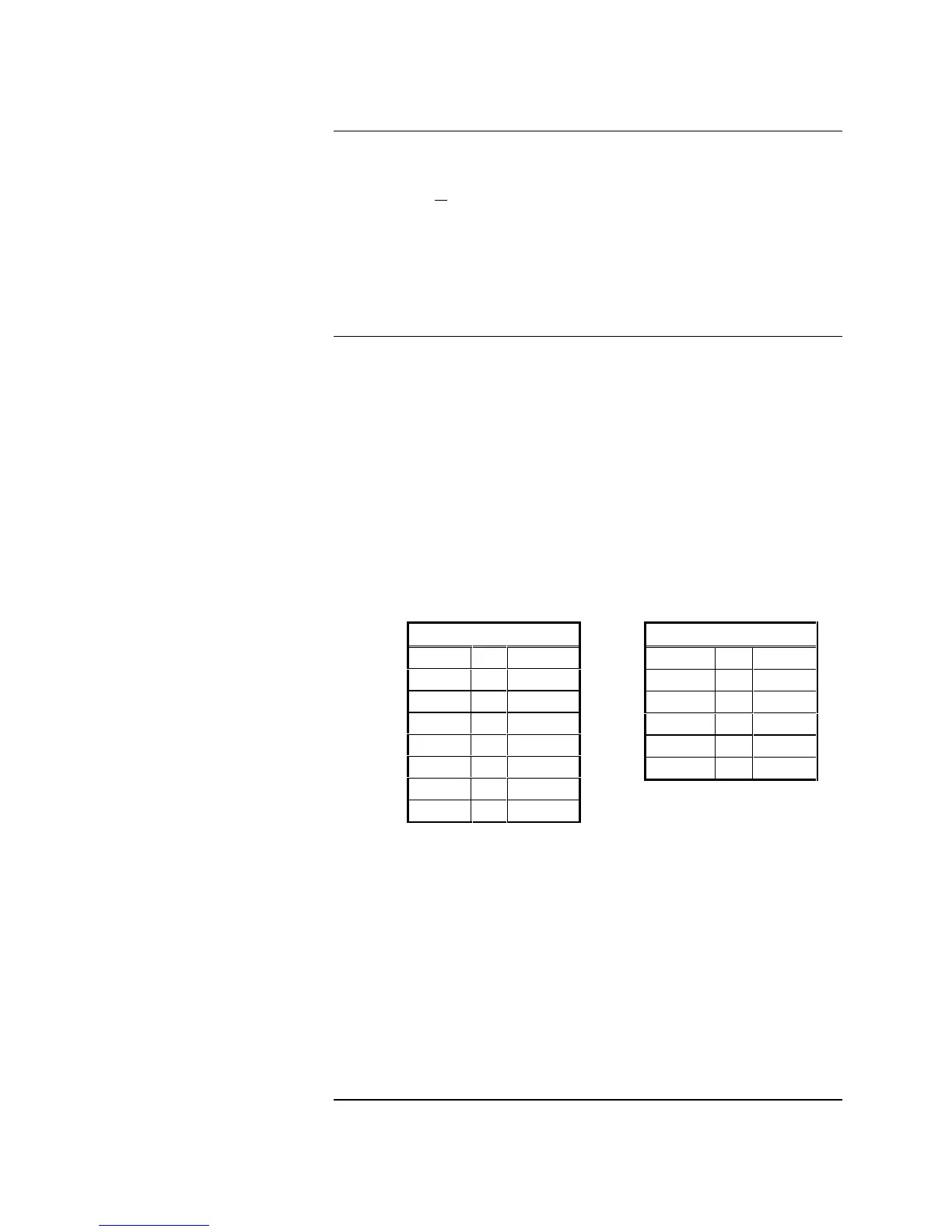
Table 1. Jumper Settings
2. Configuration of City Circuit 2 as supervisory, jump P6-1 to P6-2 and P6-3
to P6-4. Configuration of City Circuit 2 as trouble, jump P6-2 to P6-3.
Auxiliary Circuit Supervision:
To supervise AUX Zone 1 or AUX Zone 2 alarm outputs, clip JW1 on System
Board for AUX Zone 1 and clip JW2 for AUX Zone 2.
To supervise AUX Alarm output clip JW3 on System Board.
To supervise AUX Zone Alarm outputs on Zones 3 through 8, remove
JW1-JW4 on 4-IDC expander module and JW1 and JW2 on 2-IDC expander
module.
IDC or NAC configuration for optional Class A converter module - Refer to
Field Wiring Diagram 841-992 supplied with the FACP.
Continued on next page
System Modules (Continued)
Jumper Settings/Service
Switches
Remote Station
P2-2 to P2-3
P3-1 to P3-2
P3-3 to P3-4
P3-5 to P3-6
P4-2 to P4-3
P5-1 to P5-2
P5-3 to P5-4
P5-5 to P5-6
Local Energy
P2-1 to P2-2
P3-7 to P3-8
P3-9 to P3-10
P4-1 to P4-2
P5-7 to P5-8
P5-9 to P5-10