3-3
Chapter 3 NAC Power Supply
NAC Section
NAC Section
Overview
The NAC power supply allows connection to up to four Class A NAC circuits. Notification
appliances within the 4007ES system are synchronized including any attached 4009 series
NAC extenders. Do not mix Wheelock and Simplex branded devices in the same system, they
will not be synchronized. The following TrueAlert non-addressable appliances are Special
Application compatible with the NAC power supply:
- 4098-9772 Sensor Base with 520 Hz Sounder
- 4098-9773 CO Sensor Base with 520 Hz Sounder
- 4901-series Horn
- 4903-series A/V
- 4903-series S/V
- 4904-series V/O
- 4906-Multicandela series
- 49CMT series Horn
- 49CMTV series A/V
- Wheelock Series: AS, HS, NS, ZNS, RSS, RSSP, STR, ZRS, MT, AMT, MTWP, ET,
CH, E50, E60, E70, E80, E90, S8, SA
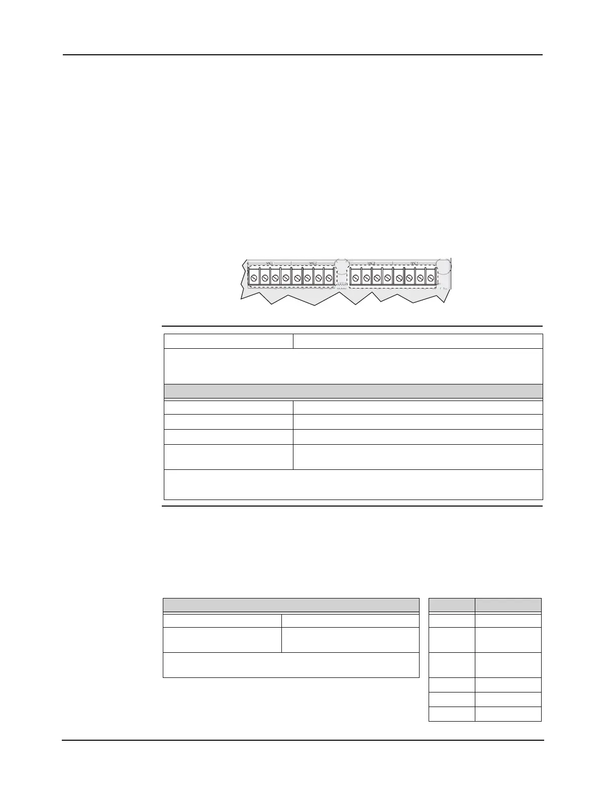
Figure 3-2. NAC Terminal on NAC Power Supply
Wiring Wiring Parameters
The NAC Power Supply is supervised and power-limited. Refer to Table 3-4 for the NACs’
supported EOL resistors and the related supervisory current and to Table 3-3 for the wiring
parameters.
Note: If a shielded wire is used, cut it and tape it at both ends.
Continued on next page
NAC1
B+ B- A+ A-
NAC2
B+ B- A+ A-
NAC3
B+ B- A+ A-
NAC4
B+ B- A+ A-
Specifications
Maximum Appliances 70 per circuit*
* Each 49CMT series appliance counts as 5 regular appliances for the maximum 70 appliances that
can be supported per NAC. As the earth fault sensitivity with thirteen MT appliances drops from 10
K to 9.6K ohms, no more than thirteen 49CMT series appliances may be placed on one circuit.
Electrical Specifications:
Voltage 24 VDC nominal
Alarm Current The maximum alarm current is 3 A per circuit.
Supervisory Current Refer to Table 3-4
Special Application Appliances
(TrueAlert Non-Addressable)
6 A total
Note: When NACs are used for Regulated 24DC appliances, maximum current per NAC is reduced to 2 A
and total power supply notification current rating is reduced to 3 A. Current used by modules pow-
ered from the 4007ES power supply must be deducted from the total current.
Table 3-3. Wiring Parameters
Table 3-4. Supported EOLR
and Supervisory Current
Maximum wiring distance EOLR Current
Maximum cable load 10,000 ft (3,048m) per channel 3.9 k 5.7 mA
Maximum wire length from
panel to any device
4,000ft (762m) 4.7 k 4.8 mA
Maintain correct polarity on terminal connections. Do not loop
wires under terminals.
5.1 k 4.4 mA
5.6 k 4.0 mA
10 k 2.2 mA
15 k 1.4 mA