2-1
Chapter 2
Installation
Introduction This chapter describes how to install the 4007ES panel. It can be semi-flush or surface mount.
Mounting the
4007ES Panels
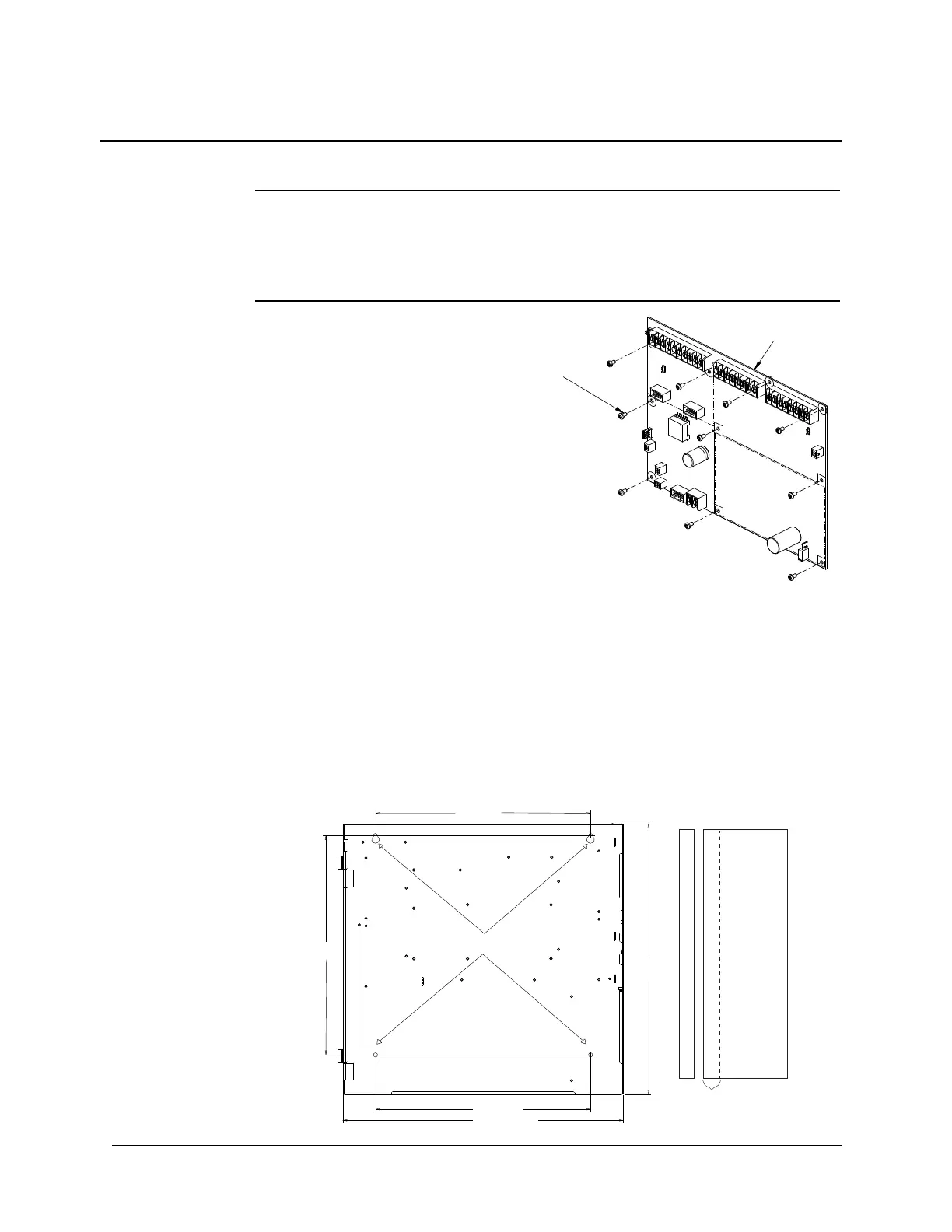
• Due to the danger of metal fragments
falling into electronics when drilling
the holes for the conduits, remove the
electronics in the system:
- To remove the electronics, unscrew
the ten screws. Remove the power
supply and store it in a safe, clean, and
dry location until the panel installation
is completed, see Figure 2-1.
- If installing a 4007ES hybrid panel,
also remove the Zone/Relay card (three
screws).
• Use a suitable punch where conduit
entrance is required. Knockouts are not
provided. Locate and create on-site as
required during installation.
Figure 2-1 Screws location
• For surface or semi-flush mounting to a wooden wall structure, the panel must be attached
with four 1-½-inch-long (38 mm) lag bolts and four ½-inch-diameter (13 mm) washers
(supplied by others).
• For surface mounting, secure the box to the wall using the tear-drop mounting holes on
the back surface. For semi-flush mounting, secure the box (along the sides) to the wall
studs. Note that the front surface of the back box must protrude at least 1-1/2 inch (38mm)
inches from the wall surface for semi-flush installation. A trim kit is supplied for semi-
flush mounting. Refer to the Trim Kit Application section for more information.
• To install the panel refer to Figure 2-2 for the dimensions and use the holes in the back
box to secure it to the wall.
.
Figure 2-2. Back Box Installation dimensions and Semi-Flush Mounting (Right)
In this chapter
Mounting the 4007ES Panels ................2-1 Trim Kit Application .............................2-2
Safety Ground........................................2-4 AC Supply Wiring .................................2-4
Battery Guidelines.................................2-4 Final Installation....................................2-5
16” (406mm)
16-5/16”
(416mm)
16’ (406mm)
20-7/8” (530mm)
20-3/16”
(512mm)
1-1/2” (38mm)
Mounting Holes