2-3
Chapter 2 Installation
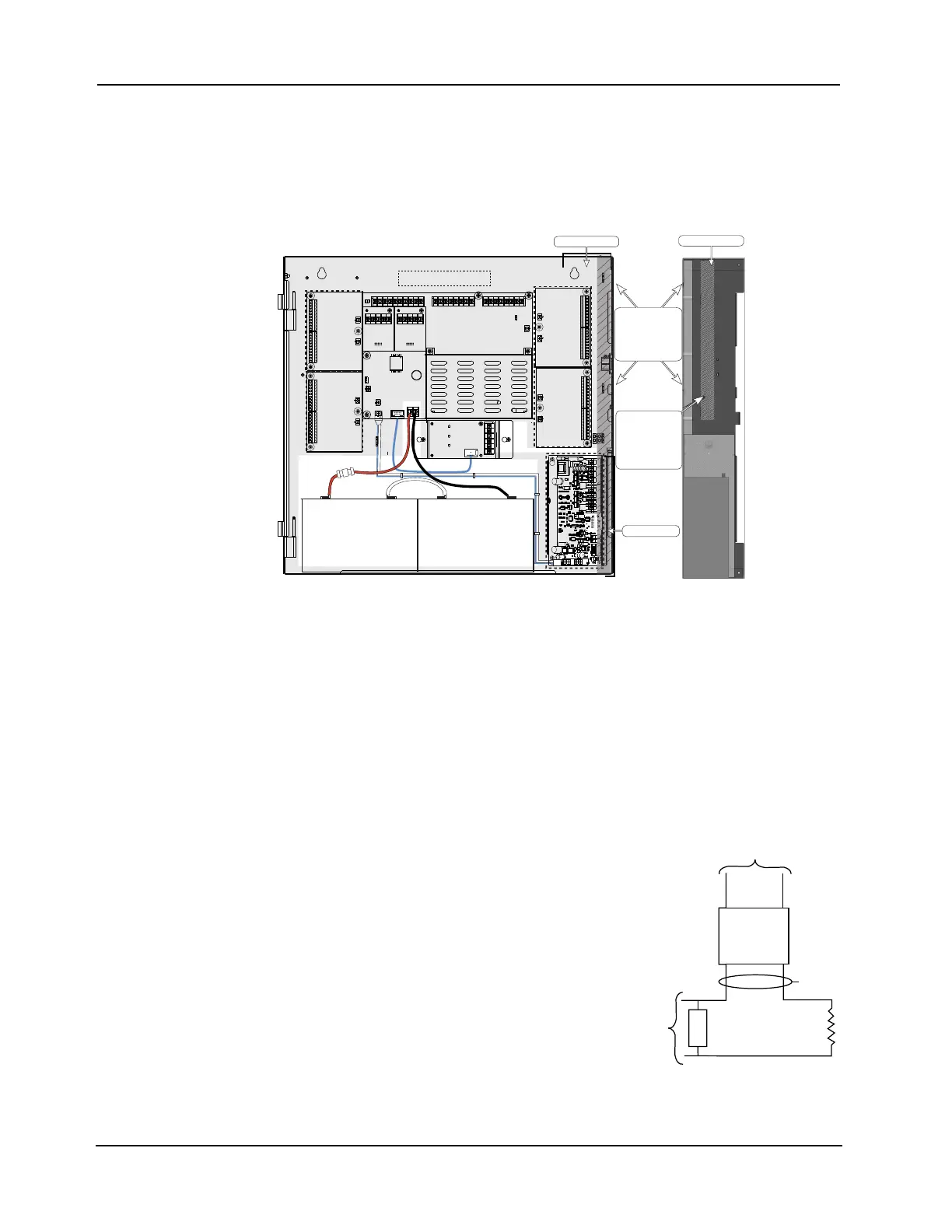
Wiring
Wiring Guidelines Follow these guidelines when connecting Power-Limited (PL) systems. For more information
about these guidelines, contact your authorized Simplex Product supplier.
• Non-Power Limited (NPL) field wiring (AC power, batteries, City connection, DACT)
must be installed and routed in the shaded areas shown in Figure 2-5.
• A minimum of 0.25 inches space must be maintained between NPL and PL field wiring.
• The AC Harness is pre-wired (tied to back of the box).
Figure 2-5. Field Wiring Guidelines (NAC Power Supply Shown as Reference)
• Conductors must test free of all grounds.
• A system ground must be provided for earth detection and lightning protection devices.
This connection must comply with approved earth detection per NFPA780.
• Splicing is permitted. All spliced connections must either be soldered (resin-core solder),
crimped in metal sleeves, or encapsulated with an epoxy resin. When soldering or crimped
metal sleeves are used, the junction must be insulated with a high-grade electrical tape that is
as sound as the original insulating jacket. Shield continuity must be maintained throughout.
• Excess slack should be kept to a minimum inside the back box enclosure. The wiring
should be neatly dressed and bundled together using wire ties.
• All wiring must be done using copper conductors only, unless noted otherwise.
• For IDNet, shielded wire is not recommended. If
shielded wires are present, cut and tape off the
shield at each end in the panel to prevent it from
coming in contact with other components. Metallic
continuity of the shield must be maintained and
insulated throughout the entire length of the cable.
• If shielded wire is used, the metallic continuity of
the shield must be maintained throughout the entire
cable length and the entire length of the cable must
have a resistance greater than 1 megohm to earth
ground. Underground wiring must be free of all
water.
• In areas of high lightning activity, or in areas that
have large power surges, the 2081-9027 or the
2081-9044 Transient Suppressor should be used on
monitor points.
Figure 2-6. EOL Relay Diagram
Optional Modules
Keep battery wiring terminals
to the front of the box. If the DACT
or the City/Relay option card is
used, run 734-306 harness
wiring on the back of the box
to maintain separation from
battery wiring.
Keep NPL wiring this
side of the box, strain
relieved to the back
of the box using the
lances shown.
Keep PL wiring in
this area for any
optional cards
mounted on this side
if NPL wiring is run
towards the top of
the box.
NPL conduit entry
NPL Conduit Entry
Side View of Panel
Note:
The 2098-9739 Relay is
used as an example.
Other UL Listed 24VDC
EOL relays can be used,
depending on the application.
TO AUX POWER
RED
BLACK
2098-9739
END OF
LINE RELAY
YELLOW
IDC
LAST IDC
DEVICE