4-3
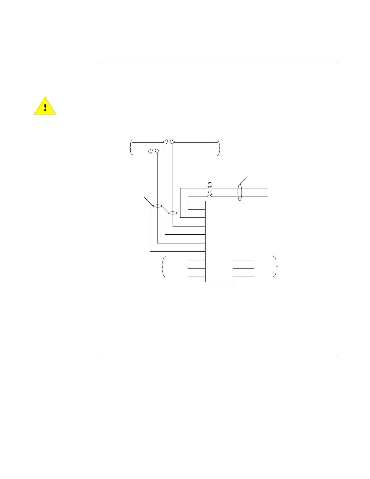
The 4098-9822 Relay Module is used with the 4098-9789, -9791, -9794, -9795, and -9796
Sensor Bases. Install the relay module using Figure 3-7 and the figure below as a reference.
IMPORTANT: Do not use a remote LED if using the 4098-9822 relay module.
The 4098-9822 relay module is not supervised and should only be
used for non-critical supplementary functions. There is a limit of
ten control outputs activated on a MAPNET II/IDNet channel. If the
channel capacity is exceeded, the relay module may not function
properly.
FigureTag FD4-709-10
FROM
PANEL
(IF USED)
+24VDC
4098-9822
RELAY
BLUE
WHITE
+WHITE
VIOLET
BROWN
GREY
YELLOW
ORANGE
GREEN
N.C.
CENTER
N.O.
N.C.
CENTER
N.O.
CONTACT A
(SEE NOTE 3)
TO OTHER 24VDC
DEVICES OR
SUPERVISORY MODULE
CONTACT B
(SEE NOTE 3)
RED
RED
BLACK
BLACK
-BLUE
+24VDC
0V0V
(SEE NOTE 1)
(SEE NOTE 2)
Figure 4-2. 4098-9822 Relay Module Wiring
Notes:
1. Do not use remote LED.
2. 18 to 32 VDC, .008 amps typical / .013 amps. Maximum.
3. Contact A or B: Dry, Form “C” - each rated 2 amps resistive at 24 VDC/0.5 amps at
110 VAC, resistive.
Continued on next page
Relay Module Accessories,
Continued
4098-9822 Relay
Module Wiring
From 4098-9789, -9791, -9794,-9795, -9796
Sensor Base