Duplex Fiber-Optic Cable Distance Specifications (566-1197, 566-1198, 566-1199, 566-1200)
The available communications distance is determined by the properties of the specific fiber cable used, the overall link topology and the
available power budget.
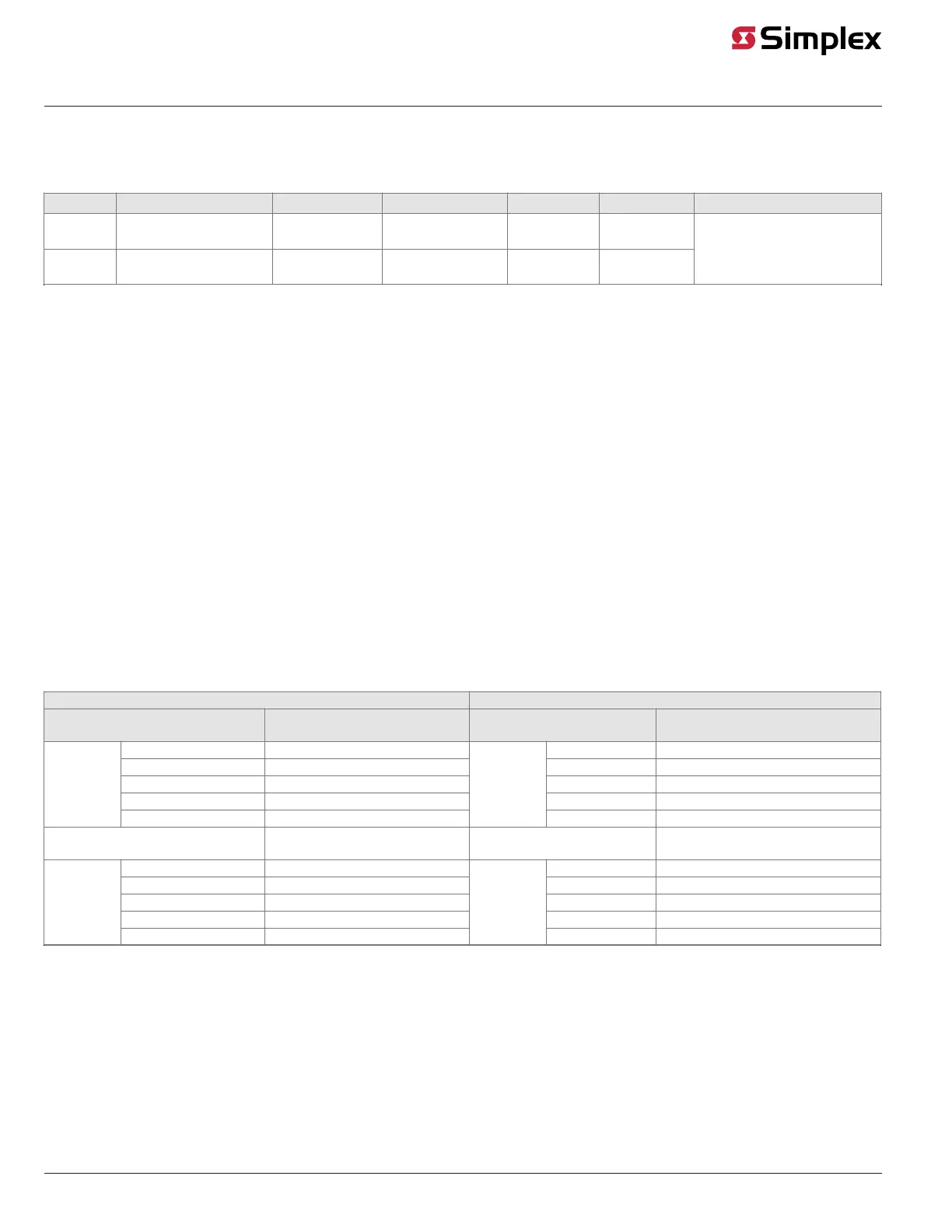
Table 7: Duplex fiber-optic cable communications distance examples
Fiber type 1 MIFL 2 Power margin Distance 3 Budget 3,5 Coupler/Slice Losses
Multi- mode 50/125 or 62.5/125
numerical aperture = 0.275
1.5 dB/km
@1300 nm
3 dB 5 km 18 dB
Single-
mode
9/125
numerical aperture = 0.2
1 dB/km
@1310 nm
3 dB 25 km 22 dB
0.75 dB max for each mated pair
0.30 dB max for each fusion
splice
for each fusion splice
Notes:
1. Fiber type: Cable specifications are for:
a. 9 micron core with 125 micron cladding, single-mode graded index fiber or
b. 50 or 62.5 micron core with 125 micron cladding, multi-mode graded index fiber.
2. MIFL: Maximum Individual Fiber Loss. Numbers shown are industry standard references. Refer to the specific cable for exact specifications.
3. Distance: The maximum distance between nodes is determined by the total loss from the transmitter to the associated receiver (fiber loss,
connector loss, splice loss and safety margin), or the maximum distance listed, whichever is smaller.
4. Wavelength: Left media = Tx 1550/Rx 1310 nm. Right media = Tx 1310/Rx 1550.
5. Link Budget: Attenuation should be measured at the following wavelengths.
a. Multi-mode @ 1300nm
b. Single-mode @ 1310nm
Wiring with the Wired Media Card
Refer to the guidelines and figures in this topic to use wired media cards.
Important: TB1 on the wired media card must not be used when it is connected to the 4100-6014 and 4100-6078 NICs.
• When the 565-413 Interface Card is used with 566-793, 565-516, 565-407, or 565-409 Network Card, TB1 on the 565-413 Interface Card
cannot be used. Connection to the motherboard is required as shown.
• The shield should only be connected at one end of the line. The shield is connected to the left port.
• When wiring leaves the building, 2081-9044 Overvoltage Protectors are required. One overvoltage protector is installed where wiring leaves
the building; another is installed where wiring enters the next building.
The following table lists the 4100U/4100ES CPU motherboard connections for the wired media card.
Table 8: 566-227 and 566-938 CPU Motherboard wired media connections
566-227 CPU Master Motherboard RUI+ CPU Master Motherboard (566-938)
Motherboard Port for Media Card
Connected to P5
Wired Media Card Connection
(Left Port)
Motherboard Port for Media
Card Connected to P5
Wired Media Card Connection (Left
Port)
TB1-4 0 V TB2-4 0 V
TB1-5 Earth ground TB2-5 Earth ground
TB1-6 INV (L-) TB2-6 INV (L-)
TB1-7 None TB2-7 None
TB1
TB1-8 NONINV (L+)
TB2
TB2-8 NONINV (L+)
Motherboard Port for Media Card
Connected to P6
Wired Media Card Connection
(Right Port)
Motherboard Port for Media
Card Connected to P6
Wired Media Card Connection
(Right Port)
TB3-1 NONINV (R+) TB3-1 NONINV (R+)
TB3-2 Reserved TB3-2 Reserved
TB3-3 INV (R-) TB3-3 INV (R-)
TB3-4 Earth ground TB3-4 Earth ground
TB3
TB3-5 0 V
TB3
TB3-5 0 V
Figure 23 shows how two CPU motherboards with wired media network cards connect to each other in the 4100U/4100ES.
page 22 579-182 Rev. V
4100/4120-6014, 4100-6078 NICs and 4100/4120-Series Media Modules Installation Instruction