Illustration
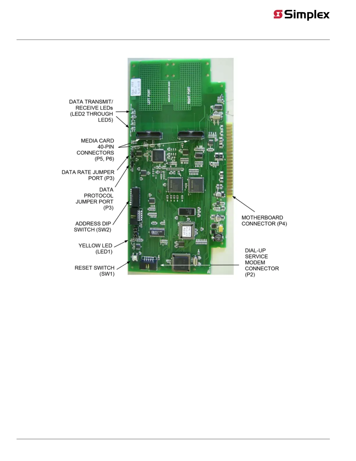
Figure 1 shows the 4100-6014 and the 4100-6078 NICs.
Figure 1: 4100-6014 and 4100-6078 NICs
NIC LED indications
The 4100-6014 and the 4100-6078 NIC modules have the following LEDs:
LED1 (yellow). Illuminates when the NIC has not established a communications link with the 4100 master.
LED2 (red). Illuminates when a data '0' is received at the left port.
LED3 (green). Illuminates when a data '0' is transmitted at the left port.
LED4 (red). Illuminates when a data '0' is received at the right port.
LED5 (green). Illuminates when a data '0' is transmitted at the right port.
Figure 2, Figure 3 , Figure 4, and Figure 5 are illustrations of four motherboards (apart from the default CPU motherboard) that can be used with the
4100 NIC.
The 565-274 Master Motherboard holds two daughter cards: the 4100 master controller card and the 4100 NIC.
The 565-275 Class B Motherboard holds the 4100 NIC by itself.
The 566-227 4100U/4100ES Master Motherboard holds a CPU card and a NIC.
The 566-398 4100ES RUI+ master motherboard holds a CPU card and a NIC.
page 3 579-182 Rev. V
4100/4120-6014, 4100-6078 NICs and 4100/4120-Series Media Modules Installation Instruction