Wiring the radar system | 27
Cable connector J connector
B (P2) J2
C (P1) J1
D (P3) J3
E (P4) J4
F (P5) J5
• Close the scanner with the screws.
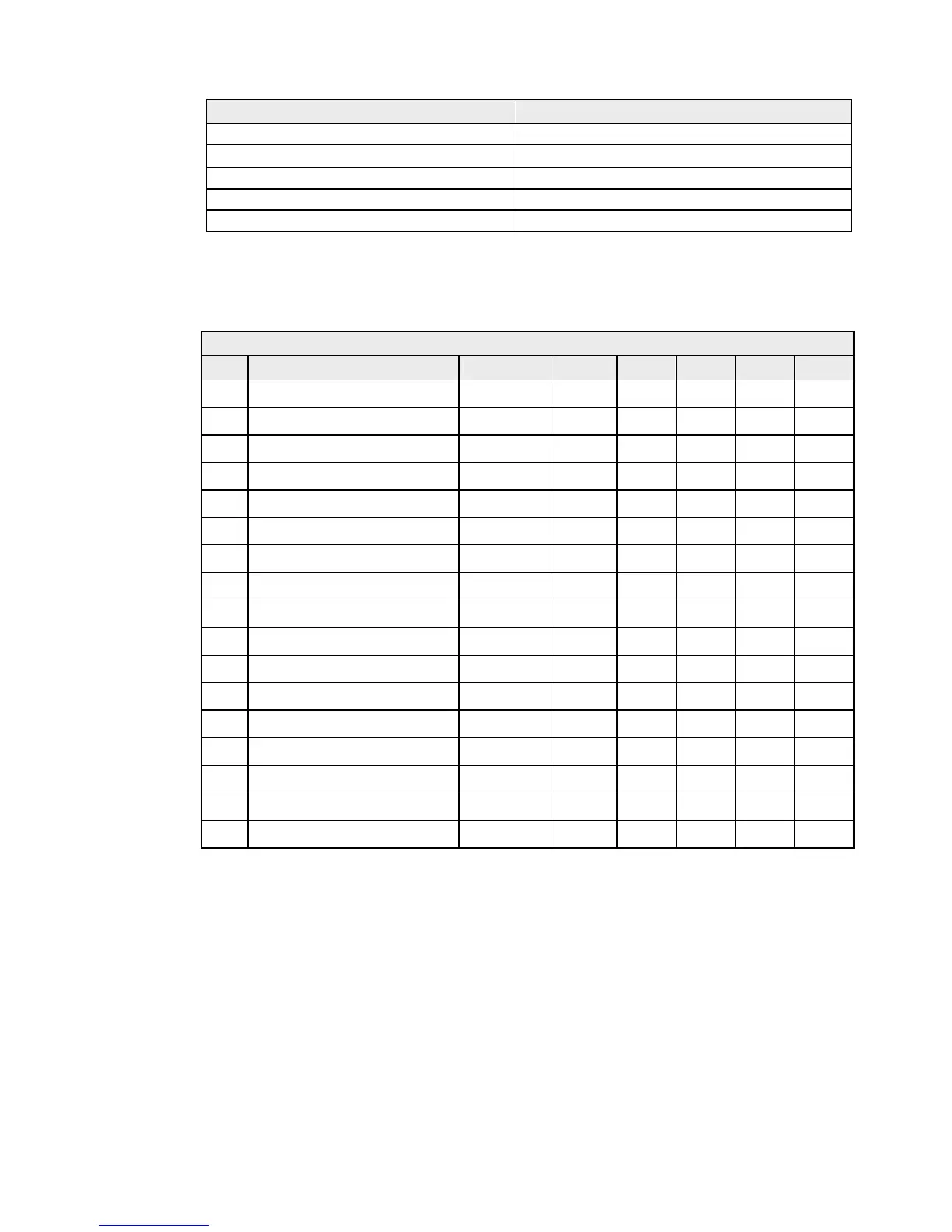
The wiring details for the connector ends B, C, D, E, and F are as follows:
AA010093/AA010094 Interconnection cable - connector ends
Pin Color/Name AWG Size B C D E F
1 Blue / Gray (Thick) #16
1
2 Purple / Brown (Thick) #16
1
3 White / Orange (Thick) #16
2
4 Red / Green (Thick) #16
2
5 Black / Sky (Thick) #16
1
6 Black #22
6
7 Drain wire (coax line) #24 2
8 No connection
9 Yellow / Pink (Thick) #16
2
10 Axis line (transparent insulation) #24 1
11 Yellow (thin) #24 3
12 Green (thin) #24
5
13 White (thin) #24 4
14 Drain wire #24
2
15 Shield line #24
1
16 Orange (medium) #22
3
Shell Braid shield