Wiring the radar system | 31
4.8 Radar processor 6 kW: Connect the interconnection cable
(AA010092) to the radar processor
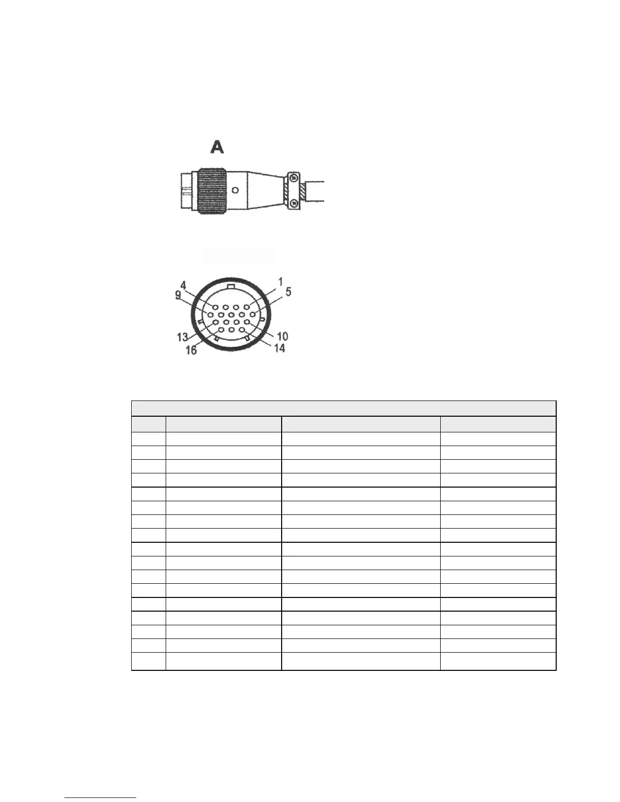
Connect the round pin end (A) of the 6 kW interconnection cable to the scanner connection on
the radar processor as follows:
6 kW Interconnection cable pin details
A Description/Remarks Color/Name AWG size
1 Scanner Ground Blue / Gray (thick) #16
2 Motor Ground Purple / Brown (thick) #16
3 Scanner Power Red / Green (thick) #16
4 Motor Power Yellow /Pink (thick) #16
5 Video Ground Drain wire (coax line) #24
6 Not used No connection
7 Not used No connection
8 Not used No connection
9 RS-485 Comm+ Yellow (thin) #24 twist pair
10 Video Axis line #24
11 Not used No connection
12 Bearing Zero Green (thin) #24
13 RS-485 Comm– White (thin) #24 twist pair
14 Trigger Ground Drain wire #24
15 Trigger Shield line #24
16 Bearing Pulse Orange (medium) #18
Shell
Braid shield