8 |
Installation | HS80/HS80A/MX575C/MX575D UserManual
Mounting orientation
The smart GPS compass outputs heading, pitch, and roll readings regardless of the orientation
of the antennas. However, the relation of the antennas to the boat’s axis determines whether
you will need to enter a heading, pitch, or roll bias. The primary antenna is used for positioning
and the primary and secondary antennas, working in conjunction, output heading, pitch, and
roll values.
¼ Note: Regardless of which mounting orientation you use, the Smart GPS compass provides
the ability to output the heave of the vessel. This output is available via the $GPHEV message.
Parallel orientation
The most common installation is to orient the Smart GPS compass parallel to, and along the
centerline of, the axis of the boat. This provides a true heading. In this orientation:
• If you use a gyrocompass, you can enter a heading bias in the Smart GPS compass to calibrate
the physical heading to the true heading of the vessel.
• You may need to adjust the pitch/roll output to calibrate the measurement if the Vector is not
installed in a horizontal plane.
Perpendicular orientation
You can also install the antennas so they are oriented perpendicular to the centerline of the
boat’s axis. In this orientation:
• You will need to enter a heading bias of +90° if the primary antenna is on the starboard side of
the boat and -90° if the primary antenna is on the port side of the boat.
• You will need to configure the receiver to specify the GPS antennas are measuring the roll axis
using $JATT,ROLL,YES.
• You will need to enter a roll bias to properly output the pitch and roll values.
• You may need to adjust the pitch/roll output to calibrate the measurement if the Vector is not
installed in a horizontal plane.
Figure 2-2 and Figure 2-3 provide mounting orientation examples.
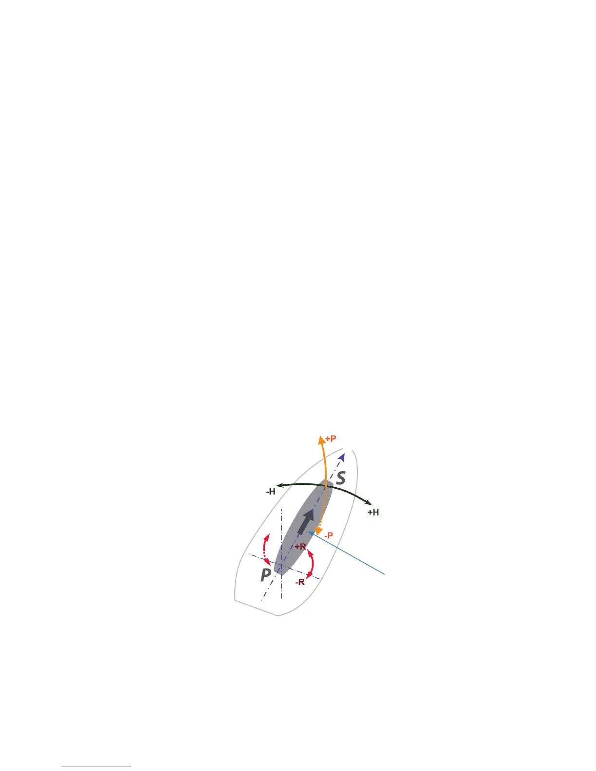
Recessed arrow located on
the bottom of the enclosure
Forward motion
Figure 2-2: Recommended orientation and resulting signs of HPR values