External Alarm Output
The MX51x Ext. alarm output connection is on pins 3 and 4 of the AUX (8-pin) cable.
They are held open (floating) during normal operations. In an alarm condition, the
external alarm pin is switched to ground potential. When an alarm condition is cleared
or acknowledged, the Ext. alarm signal will return to open condition automatically (refer
to table below for relay conditions). However, it is possible to retain the external alarm
condition by setting the “Retain external alarm:” to ON under the CFG1/Operation menu.
At this setting, the external alarm signal can only be cleared by correcting the problem.
Ext. Alarm Relay Conditions
MX51x Turned OFF Energized
MX51x Turned ON (No Alarm) Not Energized
MX51x Turned ON (With Alarm) Energized
12 VDC Input Power Failure Energized
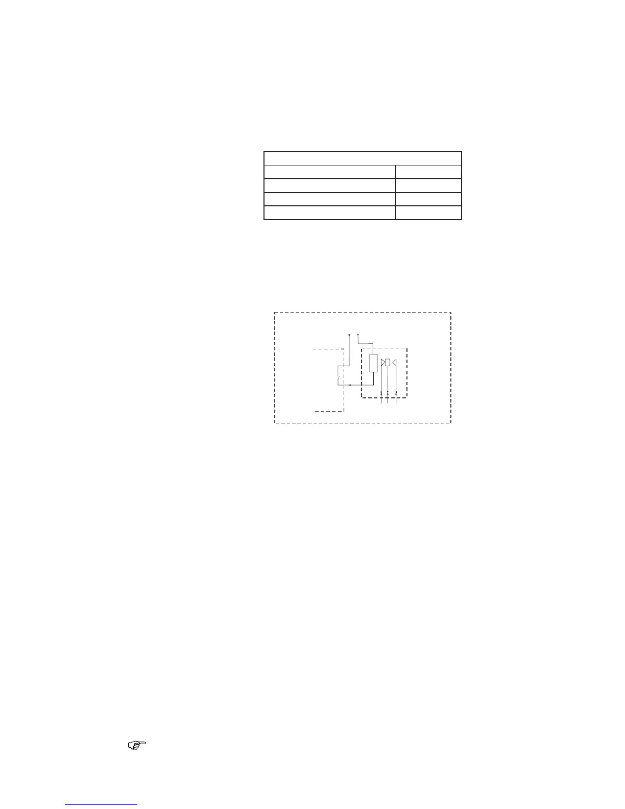
The external alarm is derived from the “EXT alarm” port on AUX cable, pin 3 (Blu) and
pin 4 (Prpl). The software is setup in each of the appropriate CFG1 (Alarms) menu. The
relay coil supply voltage must be connected to an independent battery backed-up alarm
supply. Make sure the relay coil voltage is compatible with the voltage rating of the
alarm power supply (i.e. NTE Electronics Relay - P/N R14-11D10-12 for use in a 12 VDC
supply). The negative ground of the alarm power supply must be connected to Pin 3
(Blu) of the AUX (8-pin) cable (refer to the relay diagram below).
NMEA Interface
The MX51x meets the NMEA 0183 version 2.3 electrical standard for marine interface
communications with other marine equipment, such as: Radars, Plotters, Autopilots, Fish
Finders, etc.
There are differences in the electrical interface specification between NMEA 0183 version
1.5 (introduced in 1987) and NMEA 0183 version 2.0 and later (introduced in 1994).
Some older model equipment utilize RS-232, others use RS-422, and others meet the
older version 1.5 specification.
NMEA Interface to other Equipment
The MX51x complies with the NMEA 0183 V2.3 protocol. As version V2.1 is not
necessarily compatible with the older version V1.5, the differences in hardware are
mentioned here to avoid possible conflicts:
Listener:
The listener input works with a threshold of 2 volts compared to the former 4 volt. It
is still an insulated input and, in general, there should not be any interface problems
receiving data from the older standard.
Talker:
The talker output is a RS-422 output:
NMEA talker output B is active compared to GND or shield of the navigator. In the old
version, output B was normally tied to GND or shield.
The maximum drive voltage between the talker A and B outputs is ±6 volt.
Compared to the former 0 to 15 volt output, the negative voltage between the talker A
and B output may be a problem on older listeners which do not meet the new standard.