| 11
Installation | HS80/HS80A/MX575C/MX575D User Manual
Power/Data cable considerations
Before mounting the Smart GPS compass consider the following regarding power/data cable
routing:
• Cable must reach an appropriate power source
• Cable may connect to a data storage device, computer, or other device that accepts GPS data
• Avoid running the cable in areas of excessive heat
• Keep cable away from corrosive chemicals
• Do not run the cable through door or window jams
• Keep cable away from rotating machinery
• Do not crimp or excessively bend the cable
• Avoid placing tension on the cable
• Remove unwanted slack from the cable at the Smart GPS compass end
• Secure along the cable route using plastic wraps.
Warning: Improperly installed cable near machinery can be
dangerous.
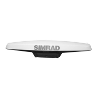
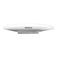
Mounting the Smart GPS compass
This section describes how to flush mount or pole mount the Smart GPS compass. Keep the
following in mind when planning your installation:
• SIMRAD does not supply mounting surface hardware or a mounting pole. You must supply
the appropriate hardware or mounting pole required to complete Smart GPS compass
installation.
• You do not necessarily need to orient the antenna precisely as you can enter a software offset
to accommodate for a heading measurement bias due to installation.
Flush mounting the Smart GPS compass
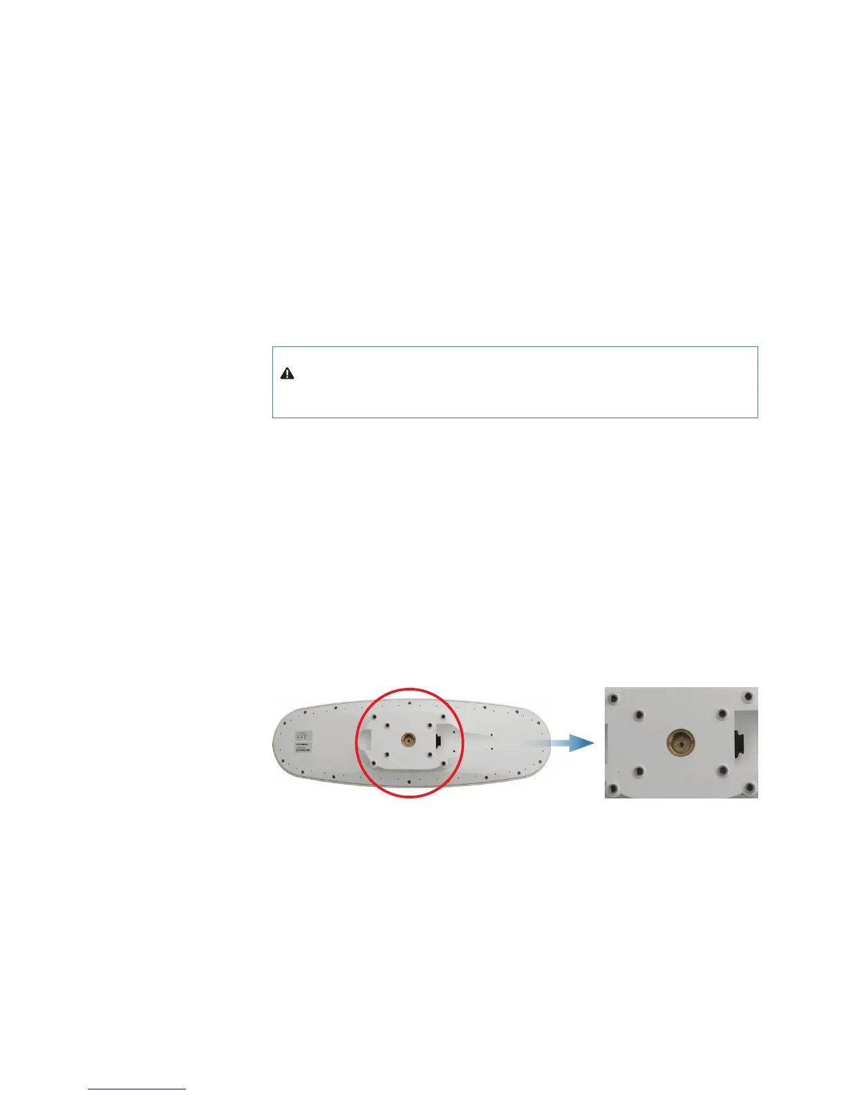
The bottom of the Smart GPS compass contains eight holes (two sets of four holes) for
flush mounting the unit to a flat surface (Figure 2-7). The flat surface may be something you
fabricate per your installation, an off-the-shelf item (such as a radar mounting plate), or an
existing surface on your vessel.
Figure 2-7: Flush mounting holes on bottom of Smart GPS compass
Complete the following steps to flush mount the Smart GPS compass:
1. Determine the desired location and proper orientation for the Smart GPS compass.
See “Mounting orientation” on page 8 for information on determining the desired
orientation.
2. Use the supplied template or photocopy the section of the Smart GPS compass that contains
the eight mounting holes (see Figure 2-7) for use as a template to plan the mounting hole
locations. Use the inner four holes or the outer four holes per your installation.
If using a photocopy make sure it is scaled one-to-one with the mounting holes on the
bottom of the Smart GPS compass.
3. Mark the mounting hole centers on the mounting surface.