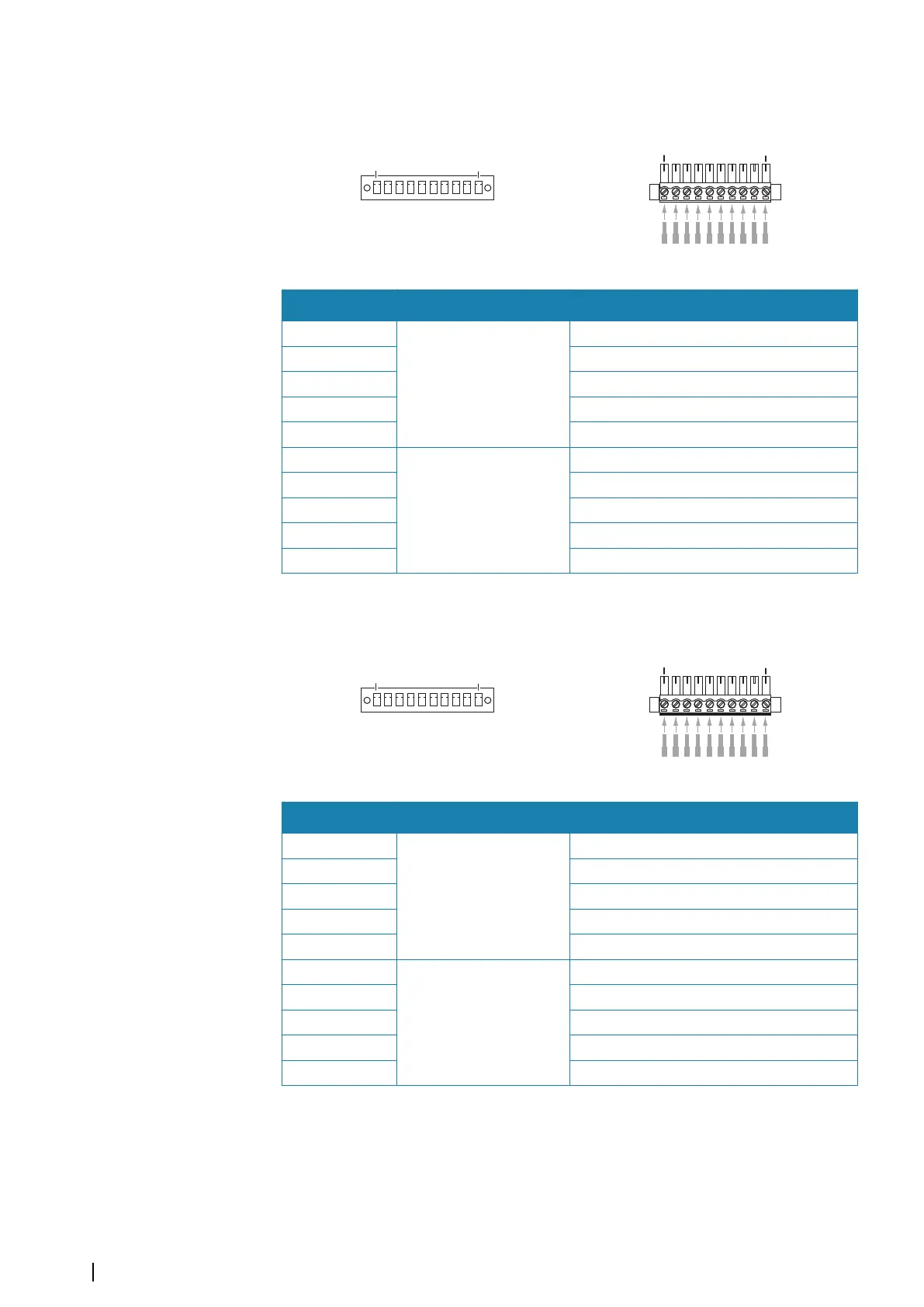
Serial 3-4
Unit socket (male)
Cable plug (female)
Pin Port Purpose
1
Port 3
(IEC 61162-1)
Listener A (Rx_A)
2 Listener B (Rx_B)
3 Shield
4 Talker A (Tx_A)
5 Talker B (Tx_B)
6
Port 4
(IEC 61162-1)
Listener A (Rx_A)
7 Listener B (Rx_B)
8 Shield
9 Talker A (Tx_A)
10 Talker B (Tx_B)
Serial 5-6
Unit socket (male)
Cable plug (female)
Pin Port Purpose
1
Port 5
(IEC 61162-1)
Listener A (Rx_A)
2 Listener B (Rx_B)
3 Shield
4 Talker A (Tx_A)
5 Talker B (Tx_B)
6
Port 6
(IEC 61162-1)
Listener A (Rx_A)
7 Listener B (Rx_B)
8 Shield
9 Talker A (Tx_A)
10 Talker B (Tx_B)
Sensor connection
Any sensor connected to the system should meet IMO performance standards and be
certified. Failure to do so would make the rest of the system non-compliant.
The system must be connected to an External Position Fixing System (EPFS), a gyrocompass/
heading sensor, and a SDME source via serial line.
12
Wiring | R5000 radar processor Installation Manual