Instruction manual
20220562E 27
Use the attached template (Fig. 3-6) to drill the required mounting
holes. The unit is fastened to the mounting base by the two Allen screws
enclosed. (Other types of screws may be used if fastened to i.e. a
wooden base.)
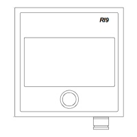
Fig. 3-3 RF45X - Mounting
Make the parallelogram configuration of the transmission link (see Fig.
3-3) with the rudder amidships and temporarily fasten the link to the
RF45X shaft. The transmission rod can be shortened by cutting off a
piece using a hacksaw. Move the rudder manually h.o. - h.o. and make
sure the transmission link is moving freely in both directions.