4.2.1 Main circuit (strong electric) terminal Introduction
Table 4-1 servo drive main circuit terminal
Control power supply
input terminals
1-phase input which is consistent with the main circuit
power supply voltage level
Main circuit AC
power input terminals
EA100-2R8-2□
EA100-5R5-2□
EA100-7R6-2□
L1, L2 1-phase 220V input
L1, L2, L3 3-phase 220V input
L1, L2, L3 3-phase 220V input
EA100-5R4-3□
EA100-□□□-3□
EA100-026-3□
External braking
resistor connection
terminals
Default connection between D and P +.
When the braking is insufficient, please keep P +, D
circuit open, and connect an external braking resistor
between the P + and C.
DC bus terminal of servo drive. It can be shared when
multi-parallel.
Connection terminals of the servo motor and they are
connected to U, V, W of the motor
One ground terminal for EA100-2R8-2A and
EA100-5R5-2A; Two ground terminals for other power
drives. It is connected to the ground terminal of power
supply and the ground terminal of motor.
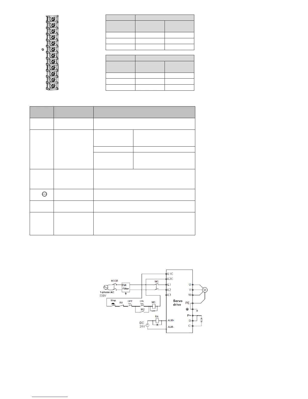
4.2.2 Power Wiring
Servo drive power connection is divided into 1-phase and 2-phase. 1-phase only for the drives with output current 7.6A and less than 7.6A
1-phase power supply wiring (rated output current ≤ 7.6A)
Figure 4-1 1-phase power supply wiring diagram
3-phase power supply wiring (all series are applicable)
 Loading...