32
4.7 Holding brake
When the motor is used to vertical axis or similar situation, in order to protect the moving parts when loss power, you should use motors with
holding brake.
1. The holding brake is used only to keep the motor stopped, not for stopping the running motor
2. When motors with holding brake running, there may be a clicking sound; it does not affect the function.
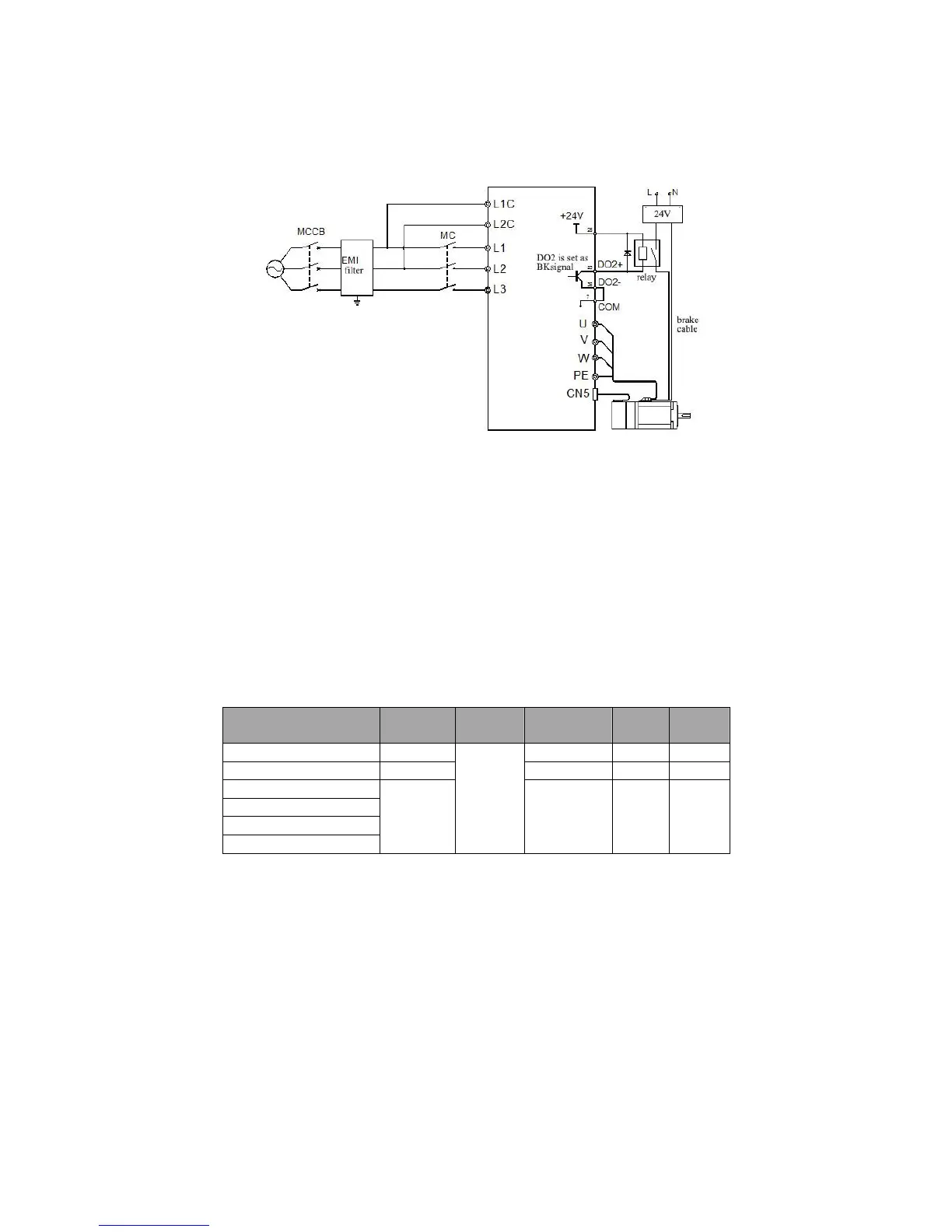
Holding brake need an external 24V power supply, brake signal and brake power supply wiring as follows.
Figure 4-20 brake signal and brake power supply wiring
4.7.1 Holding brake Wiring Precautions:
1) The 2nd function (BK) signal terminals (DO2 +, DO2-) should be used to control the intermediate relay. The power supply of brake is
controlled by turning on or off the intermediate relay.
2) There is no polarity of the brake coil, when the brake powered on it is in release state.
3) Be sure to use an external power supply for brake. For Intermediate relay, it can be powered by servo drive internal DC24V,and it is
suggested that don‘t use the one DC24V power supply for both brake and relay
4) When using external power for relay coil, please note DO2 + terminal should be connected to the positive terminal, DO2- terminal
connected to the negative terminal.
5) The input voltage of brake should be at least 21.5V. And it is recommended to use cable more than 0.5mm
2
considering the voltage drop
on the cable. Brake specific parameters in Table 3-11.
6) Brake should not to share power supply with other electrical appliances to avoid voltage drop which can lead to braking malfunction.
Table 4-11 Brake datasheets