5
HTE302172
33/46
6
Note: Two external rheostats or a current control must have been wired before the function
cord “rnt X” will be set for “X=2” or “X=1”.
Note: “Panel” in the table means running by stored data, the stroke and
the driving frequency.
Note: On the maximum setting of the external rheostat the stroke data appears
on the display is not “100” but “over 95”.
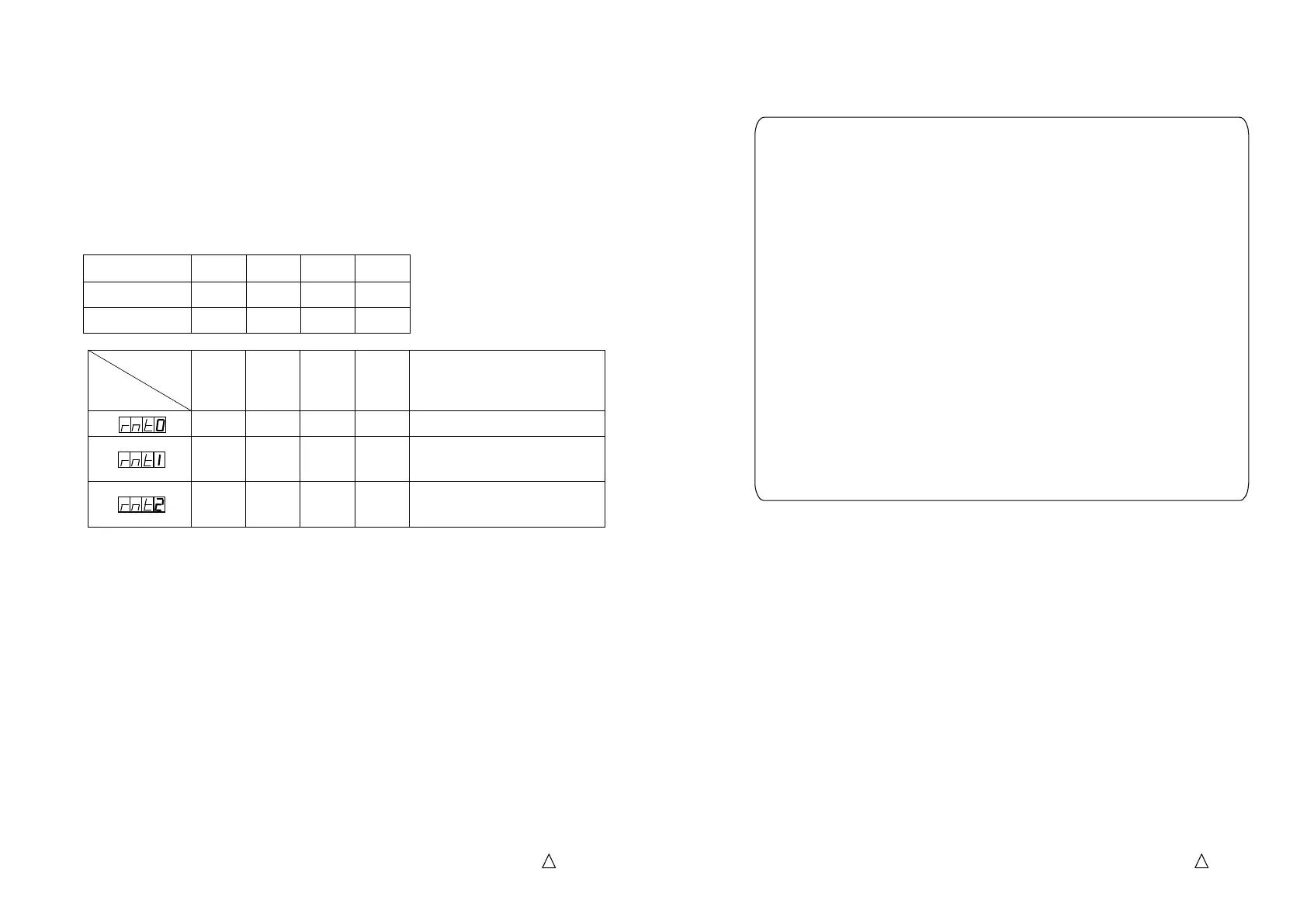
Combination No.
Function code
0 1 2 3 Remarks
Panel Panel Panel Panel Running by the stored data
4-20mA
Panel Panel Panel
The Combination No.0 determines
running by 4 – 20 mA current
control.
VR1 VR2 Panel Panel
The combination No.1 and 2
determine running by the exte
rheostats. See note below.
Speed Change Signal
Speed Change SignalSpeed Change Signal
Speed Change Signal
Combinations of “Open” or “Close” between terminals “COM” and“N1”, and “COM” and “N2”,
with contacts provided by customer, determines “Combination No.” See table below.
Combination of “Combination No.” and Function “Remote” determines behavior of C10-controller.
Combination No. 0 1 2 3
N1 and COM Open Close Open Close
N2 and COM Open Open Close Close
5
HTE302172
34/46
6
Note 1: After stored the stroke the partsfeeder runs by it even if the external signal “N1”
and “N2” are changed.
Data of stroke, drive frequency, soft start ramp-up time and on delay and off delay
times are stored for each Combination No.
Note 2:When the drive frequency is reset on Combination No.1 to 3, the partsfeeder must
be stopped and then change the external signals “N1” and “N2”.
How to store the Speed Change Signal
How to store the Speed Change SignalHow to store the Speed Change Signal
How to store the Speed Change Signal
Please follow the procedure below to set the Combination No.1 to No.3.
The procedure must start on the Combination No.0 or open the terminals “Com” and“N1”
and “Com” and “N2”.
1.
Set and save the stroke on the Combination No.0.
2.
Running the partsfeeder, input the external signal “N1” and “N2”
the Combination No.
After the action the Combination No. appears on the display as “SP-X” for “
or 2 or 3” for two seconds.
The drive frequency is that is set on the Combination No.0.
Caution:
Caution: Caution:
Caution: If the input signal “N1” and “N2”
are changed while the partsfeeder is
stopping the drive frequency stored is cleared and replaced with
the maximum.
3.
Dial the setting dial and select “Stroke” and set the stroke required with
the setting encoder.
4.
Push “Save”
button to store the data. After that the Combination No. stored appears
on the display for two seconds as “SP-X” for “X=1, 2, 3”.
 Loading...