TOP
END
OF
STUD
COLLAR
LOWER
END
OF
SLEEVE
NEEDLE
BAR
FRAME
LOCK
NUT
COLLAR
SET
SCREWS
SLEEVE
NUT
HEAD
OF
STUD
BEVELED
SECTION OF
LOWER
STUD
SHOULD
NEVER
PROTRUDE
ABOVE
TAPPED
HOLE
IN
CASTING
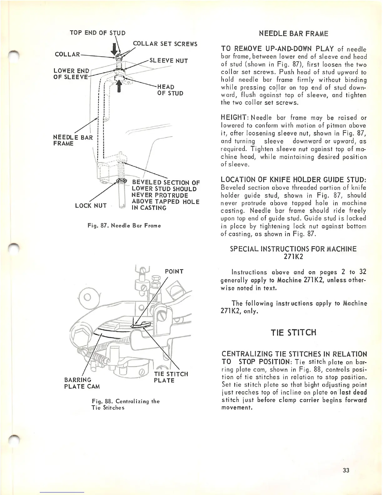
Fig.
87.
Needle
Bar Frame
BARRING
PLATE
CAM
o
POINT
TIE
STITCH
PLATE
Fig.
88.
Centralizing
the
Tie
Stitches
NEEDLE
BAR
FRAME
TO
REMOVE UP-AND-DOWN
PLAY
of
needle
bar frame, between lower end of
sleeve
and head
of stud (shown in Fig. 87), first loosen the two
collar
set
screws. Push head of stud
upward
to
hold needle bar
frame
firmly
without binding
while pressing collar on top end of stud
down
ward, flush against top of sleeve, and tighten
the
two
collar
set
screws.
HEIGHT: Needle bar frame may be raised or
lowered to conform with motion of pitman above
it, after loosening
sleeve
nut, shown in Fig. 87,
and turning sleeve
downward
or upward, as
required. Tighten sleeve nut against top of ma
chine head, while maintaining desired position
of
sleeve.
LOCATION
OF
KNIFE
HOLDER
GUIDE
STUD:
Beveled section above threaded portion of knife
holder guide stud, shown in Fig. 87, should
never protrude above tapped hole in machine
casting.
Needle bar frame should ride freely
upon top end of guide stud. Guide stud
is
locked
in place by tightening lock nut against bottom
of casting, as shown in Fig. 87.
SPECIAL
INSTRUCTIONS
FOR
MACHINE
271K2
Instructions above and on pages 2 to 32
generally apply to Machine
271K2,
unless other
wise
noted
in
text.
The following instructions apply to Machine
271K2, only.
TIE
STITCH
CENTRALIZING
TIE
STITCHES
IN
RELATION
TO
STOP
POSITION:
Tie stitch plate on bar
ring plate cam, shown in Fig. 88, controls posi
tion of tie
stitches
in relation to
stop
position.
Set tie stitch plate so that bight adjusting point
just reaches top of incline on plate on lost dead
stitch
just before clamp carrier begins forward
movement.
33