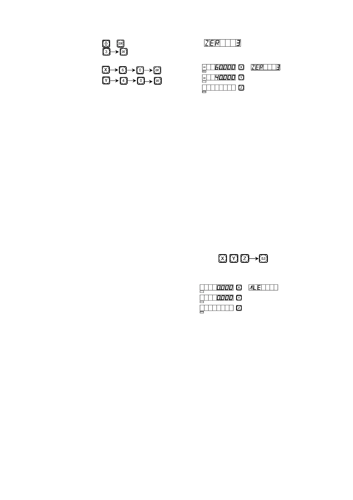
6) Enter the display mode of the third UCS.
Key or
Key
7) Enter the display mode of the third zero position.
Key
The setting of all the subsidiary zero positions of the working piece
shown in Fig. (1) has been finished.
Why the enter position coordinates of every subsidiary zero position are
just in the opposite direction of the displayed values? Let us explain this with
the above example. Under the UCS mode, when the coordinates of the
subsidiary zero position are entered at the position of the zero position in the
absolute mode, the displayed data will be the position of the zero position in
the absolute mode in the corresponding UCS. This is because the subsidiary
zero position is taken as the original point of the UCS under the relative
display mode. In Fig. (1), we can see that Point O is at the position(-80, -30)
with respect to Point 1, (-70, -40) with respect to Point 2, and (-60, -40)with
respect to Point 3. If the operator enter the coordinates of a subsidiary zero
point other than the zero position in the absolute mode, the displayed data will
be the position with respect to subsidiary zero point in the corresponding UCS.
For example, when the position of the third subsidiary zero position is entered
at Point E, the resulted display will be (-50, -30).
Method 2: Clearing when the position is reached. When the machine
tool is at the position of the subsidiary zero point, key .
We take the working piece shown in Fig. (1) as example again: Move the
machine table to the center point O shown in Fig. (1).
1) Enter the absolute display mode, reset,
set the zero position in the absolute mode
at the main reference point.
6
6
7
I
6
SEL
SEL
SEL
SEL
SEL
SEL


 To Next Page