51
UMSTELLUNG VOM TRANSPORT-
INS ARBEITSSTELLUNG
y Das Maehwerk mittels hydraulischen
Zylinder Pos. 2 parallel mit dem
schlepper greade Stellen (Bild 14).
y Anziehen den Haken, die Mähebalken in
Transportposition greift. Durch das
Ziehen am Seil wird die
Transportverrigelung gehoben (Bild 6).
Dadurch wird das Mähwerk in die
rbeitsstellung gebracht. Achten Sie
dabei auf die Sicherheit (Bild 7, 8).
y Abstand zwischen Gelenkwelle und
Boden einstellen an 515 mm (Bild 1).
y Federn Pos. 8 (Bild 1) entlastet den
Mähbalken. Mit Schrauben Pos.11
stellen Sie den Druck an Boden ein.
Fallende Gewicht (Druck an Boden)
beträgt 50-70 Kg.
y Während dem Mähen wird der Mäher
nicht mit Schlepperhydraulik
höhenverstellt, sondern werden alle
Manöver mit Hydraulikzylinder erledigt,
so dass der Abstand zwischen den
Boden und die Gelenkwelle konstant auf
515 mm erhalten bleibt.
y Da in der Transportlage das Mähwerk
hinter den Schlepper geschwenkt werden
kann, ist das Winkelgetriebe Pos. 4
(Bild 14) pendelnd montiert.
Die Winkelgetrieben- Pendlung ist durch
mechanischen Mechanismus Pos. 5
(Bild 14) ermöglicht.
ALTERNATION OF MOWER FROM
TRANSPORT – INTO WORKING
POSITION
y Put the mower by hidraulic cylinder pos.
2 in parallel position with the tractor
(fig. 14).
y lift the hook that holds the mower in the
transport position by pulling the string
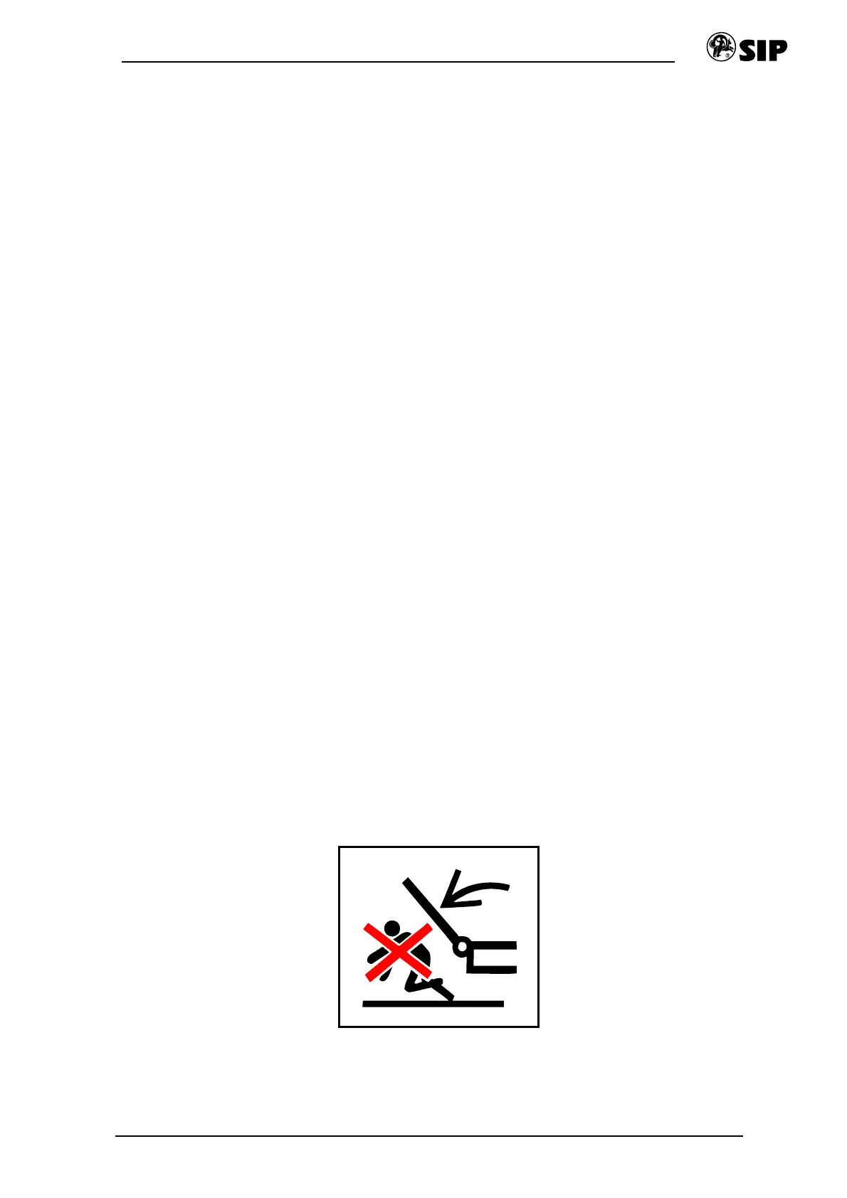
(fig.6). Lower the mower into the working
position. Pay attention to the safety!
(fig.7, 8).
y Make sure that the distance between the
ground and the P.T.O Shaft of the mower
is 515 mm (fig. 1).
y The springs pos. 8 (fig. 1) disburden the
cutter-bar. The pressure of the cutter-bar
to the ground is to be adjusted by
screws pos. 11. Recommended weight is
50-70 kg.
y Do not lift or lower the mower by tractor
hydraulics while mowing. Use hydraulic
cylinder instead and make sure that the
distance between the ground and the
P.T.O. Shaft remains constantly on
515 mm.
y Due to the fact that the mower is swang
into transport position, behind the tractor,
the angle - gear box pos. 4 (fig. 14) is
mounted on oscillating plate.
Mechanical mechanism pos. 5 (fig. 14)
control oscillating the angle gear box.
Bild 8 Fig. 8