21
4.7.2 ST-102-C2P power input and signal connector, X3
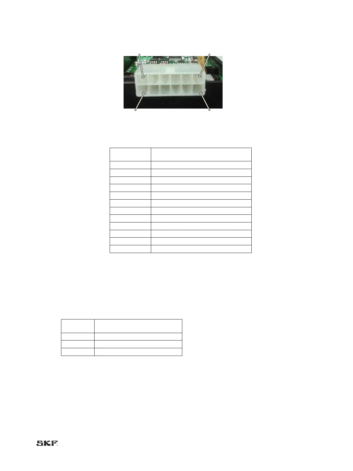
Image 2. Connector X3
Electrical connections, Molex connector (X3)
Supply voltage (+), 12 V DC or 24 V DC
Supply voltage (), 0 V DC
Pulse sensor, channel 1 (+)
Pulse sensor, channel 2 (+)
Multilube valve control (+)
Multilube pump control (+)
Multilube low limit switch (+)
Multilube heating control (+)
4.7.3 External alarm indicators (J6)
Two external indicators (max: 5 W) can be connected to the J6 connector. When the system is in alarm status, indicator
output voltage is on. The output voltage corresponds to the ST-102 control voltage. If a single indicator is
used for both alarms, outputs 1 and 3 can be connected together.
Alarm output connector (J6)
Alarm output 1 (+), pulse alarm
Alarm output 2 (+), low-level alarm

 Loading...