22
Technical information
Operating temperature range
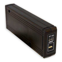
26 x 60 x 160 mm (w x h x d)
12 or 24 VDC
(10.5 to 32 VDC)
Depends on the lubrication system being controlled, 0...4 A
Self-resetting fuse, 4 A, on the circuit board
2 pcs, pulse input from the progressive distributor
Lubricant reservoir low level switch
10 to 32 VDC, 12 mA max.
Pump control, 5 A max.
Line valve control, 2 pcs, 2 A max, or
Line valve control, 1 pc, heating control, 1 pc, 2 A max.
12-pole Molex w/ power supply and control outputs
Three-pole screw terminal for alarm indicators, 2 pcs
Function button and three indicators: 1, 2 and P
Alarms are indicated with indicators above the function button
- Pulse alarm, connection for indicator, 5 W max.
- Reservoir low level alarm, connection for indicator, 5 W max.
Lubrication control programmes
Using selector switches on the circuit board
Lubrication parameter setting
Set with the function button
Lubrication cycle, pressurisation time, pulse count
For both channels
Lubrication parameters, lubrication programme status
EN61000-6-4, EN61000-6-2
CISPR 25, 30...1000 MHz
ISO 11452-2, 100...2000 MHz
ISO 11452-4, 20...200 MHz
ISO7637-2: 1, 2a, 2b, 3a, 3b, 4

 Loading...