19
4. MAIN COMPONENTS
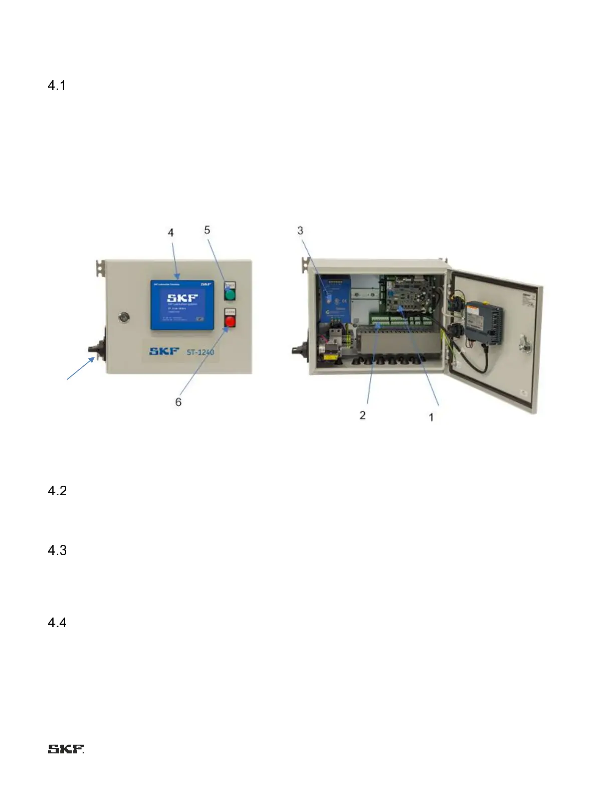
Main parts
Main parts of the ST-1240-GRAPH control centre are:
- main switch (pos. 7) on the side of the casing
- indicator lamps: a green indicator lamp for power (pos. 5) and a red indicator lamp for alarm (pos. 6) on the casing
cover
- HMI control panel (pos. 4) on the casing cover
- printed circuit board CB-105 (pos. 2) includes connectors for connecting the I/O connections for lubrication systems
- printed circuit board ST-105 (pos. 1) is the control unit of the centre
- power supply 115VAC, 230VAC/24VDC, 10A (pos. 3) for the centr
system
Photo: Main parts
HMI Control panel
The HMI control panel is used to monitor and control the lubrication, to reset alarms and to monitor lubrication phases, set
lubrication parameters, initiate extra lubrication.
Indicator lamps
The centre cover has a green and red indicator lamp.
The green indicator lamp is always on when the power is on. The red indicator lamp for alarm indicates the status of a centre-
specific alarm relay, with the exception of when the centre is potential-free / power is off.
Connection terminals
All the centre terminals, not including voltage supply (Connector X0), are located on the printed circuit
board CB-105.