Page 21
ERGON SERVICE • REV0
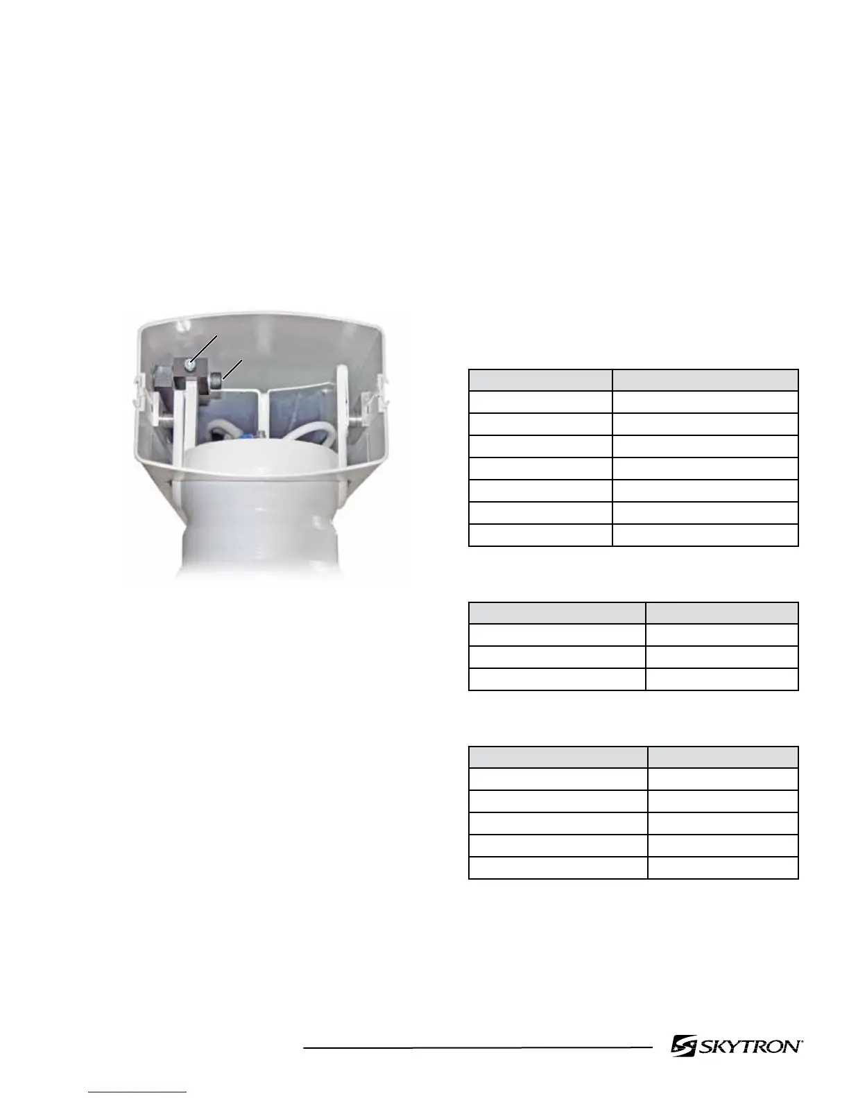
f. Plumb Adjustment
Thelowerverticalsupporttube(VST)andcarrier
shouldbeperpendiculartotheoor.Thisadjustment
should be made with all the equipment set in
place. The carrier/utilities dispensing end of the
heightadjustableradialarm hasacamadjuster
forsettingtheplumbofthelowerVST.Usethe
followingproceduretosettheplumboftheVST.
Refertogure5-12.
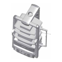
RETAINING BOLT
ADJUSTMENT BOLT
111307.03mj_2
Figure 5-12. Plumb Adjustment
1. Place the arm in the level position.
2. Usingaspiritlevel,checktheplumbof
the VST with the level positioned under the radial
arm.
3. If an adjustment is necessary, remove
the end cap from the end of the arm and loosen
thelargeretainingbolt.Turntheadjustmentbolt
as needed to obtain proper alignment. Tighten
theretainingboltsecurelyoncetheadjustmentis
complete.
5-4. Manual Height Adjustable Arm Spring
Tension Adjustment
Themanualheightadjustablearmusesgasspring
cylinderstosupplythetensiontobalancethearm.
Oneortwogasspringsmayberequiredtobalance
the arm depending on the weight of the carrier and
equipmentbeingsupportedbythearm.Usethe
following charts (Figure 5-13.) to determine the
propergasspringcongurationrequired.Inaddition
to the carrier weight, make sure to include the
weight of any accessories, monitors or equipment
thatmaybemountedonshelveswhendetermining
the proper gas springs.
Gas Spring Weight Capacity
Spring Weight Range LBS
2000N 23-56
2500N 40-76
3000N 52-117
3500N 68-143
4000N 75-146
4500N 111-160
5000N 133-183
Available Gas Springs
Spring Force Part Number
1000N H2-030-27
2000N H9-502-09
2500N H9-502-10
Carrier Weight
Carrier Weight LBS
VBM24 31
VBM36 40
UB 68
UB-1 88
FCM3 77
Figure 5-13.
 Loading...


