Page 24
ERGON SERVICE • REV0
5-6. AFS Flatscreen Arm Series Adjustments
During any maintenance or adjustment procedure,
checkallattachinghardwareforpropertightness.
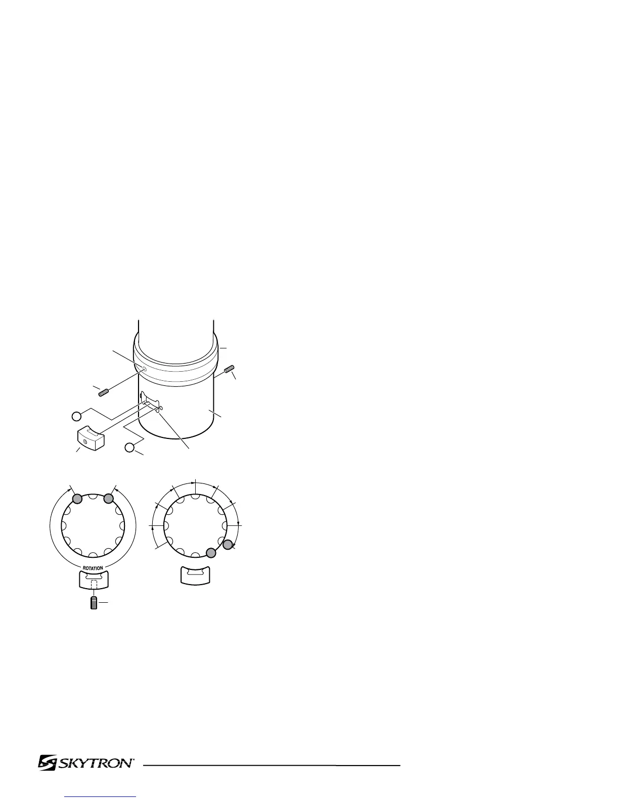
a. Flatsceen Arm Bearing Stop Assembly
CAUTION
It is necessary to support the arm
assembly prior to removal of any
hardware. Failure to do so will result
in the inadvertent release of the arm.
1. Remove set screws securing Stop
Collar.Refertogure5-18.
Figure 5-18.
2. Remove Stop Key and Stop Balls (2).
3. Determine new Stop Ball placement.
4. Installstopballsandstopkey.Alignthe
stop collar so the through hole lines up with the set
screwholeinthestopkeyandinstallthesetscrew.
NOTICE
DO NOT overtighten the set screw, it is
usedtoadjustthefrictionbraketension.
5. Tighten the set screw to set the friction
brake. The atscreen arm should move easily
throughitsrangeofrotationwithoutbindingand
hold its position when released.
STOP
COLLAR
OUTER
BEARING
HOUSING
SET
SCREW
KEYWAY
THROUGH
HOLE
SET SCREW
(FASTENS
INTO STOP
KEY)
SET
SCREW
BALL
STOPS (2)
STOP KEY
DEGREE OF ROTATION
15° TO 255°
IN 15° INCREMENTS
15
45
75
105
135
165
195
225
255
ROTATION POSITION
*
*
ONE BALL ALLOWS 270° ROTATION
 Loading...


