Page 30
ERGON SERVICE • REV0
a. AFC Arm Limit Stops
The Arm has a stop mechanism that limits the
upward movement to 20°. Use the following
procedure to allow up to 40° of upward movement.
Refertogure5-30.
b. AFC Arm Plumb Adjustment
TheVerticalSupportTubeandatscreenmonitor
orequipmentshouldbealignedperpendicularto
the oor throughout the range of movement of
the height adjustable arm. Check the plumb of
theVertical SupportTube anduse thefollowing
proceduretoadjustifneeded.Refertogure5-31.
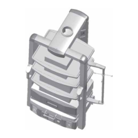
PROTECTION
PLATE
cable route
ROUTE CABLES ON TOP
SECTION OF ARM TO
AVOID PINCH POINTS
20° STOP
SCREW
PIVOT
CAP
Figure 5-30. AFC Arm Limit Stops
1. Remove the two screws securing the
side caps on the end opposite the equipment and
remove the side caps.
2. Remove the attaching screws and
remove the Pivot Cap and Protection Plate.
CAUTION
Do not remove the vertical travel stop
boltsiftheequipmentisnotinstalled.
Removing the stop bolts without the
weight of the equipment will result
in damage to the plumb adjustment
system.
3. Remove the two Stop Screws (one on
each side).
4. Replace the side caps.
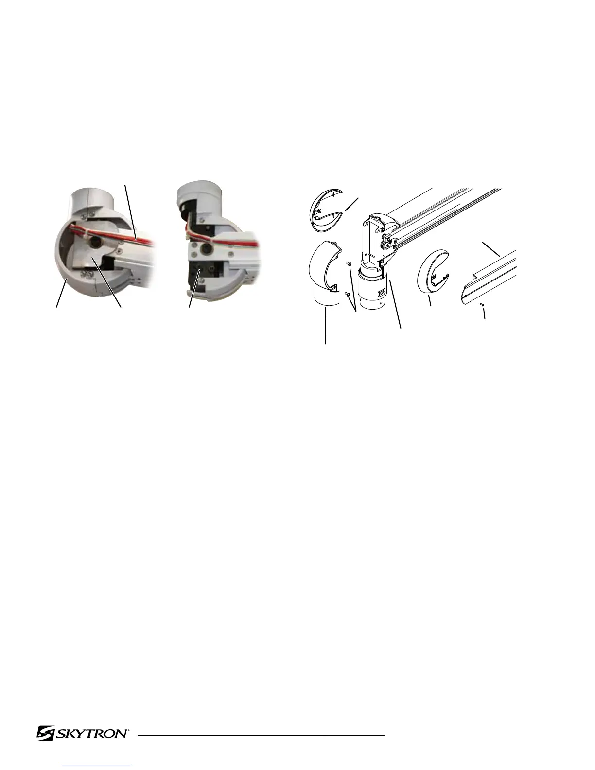
Figure 5-31. VST Adjustment.
Theplumbadjustmentshouldbedonewithallthe
equipment in place and after the spring tension
hasbeenadjusted.
1. Remove the screws securing the side
caps on the equipment end of the arm and remove
the side caps.
2. Remove the screws securing the side
covers and remove the covers.
3. Placethearmparalleltotheoor,check
the arm position with a level placed on top of the
arm.Placeanotherlevelontheverticalsupporttube.
SIDE END CAP
SIDE CAP
SCREW
SIDE END
CAP
LOWER
BEARING END
PIVOT
CAP
SCREW
PIVOT CAP
vst adjustment
 Loading...


