5 SYSTEM INTEGRATION
In the case of cables soldered directly to the readhead, the user or system integrator is
responsible for providing adequate strain relief.
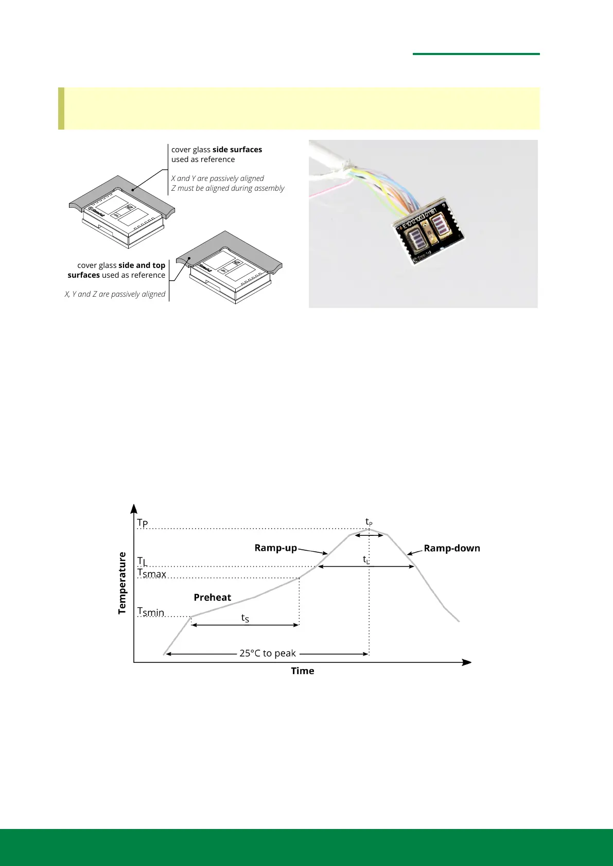
cover glass side surfaces
used as reference
X and Y are passively aligned
Z must be aligned during assembly
cover glass side and top
surfaces used as reference
X, Y and Z are passively aligned
Figure 5.3: Mounting reference for direct attachement.
5.2 METIRIO Readhead Soldering Precautions
The read head and the circuit board form a unit. The designer of the circuit board has to ensure
that this unit has proper mechanical interfaces for mounting.
Thermal performance is directly linked to the PCB design and operative environment. Careful
attention to the PCB thermal design is required. The junction from the thermal resistance to the
ambient air is θ
JA
= 130 K/W. Measurements have been conducted based on the JEDEC JESD51-2A.
Figure 5.4: Soldering Profile (Pb-free)
When soldering, ensure there is no foreign matters adhering to the surface of the readhead. After
soldering, it is advised that no mechanical stress or strong vibration is applied until the device has
reached room temperature.
www.smaract.com | Page 47Metirio Encoder User Manual
 Loading...