5 SYSTEM INTEGRATION
5.3.2 Alignment to Rotary Scales
The same rules for installation apply to rotary scales as to linear scales, but the position tolerances
might be reduced depending on the diameter of the scale. The smaller the diameter, the smaller
the installation tolerances. Here the worst case tolerances for the smallest diameter are given. In
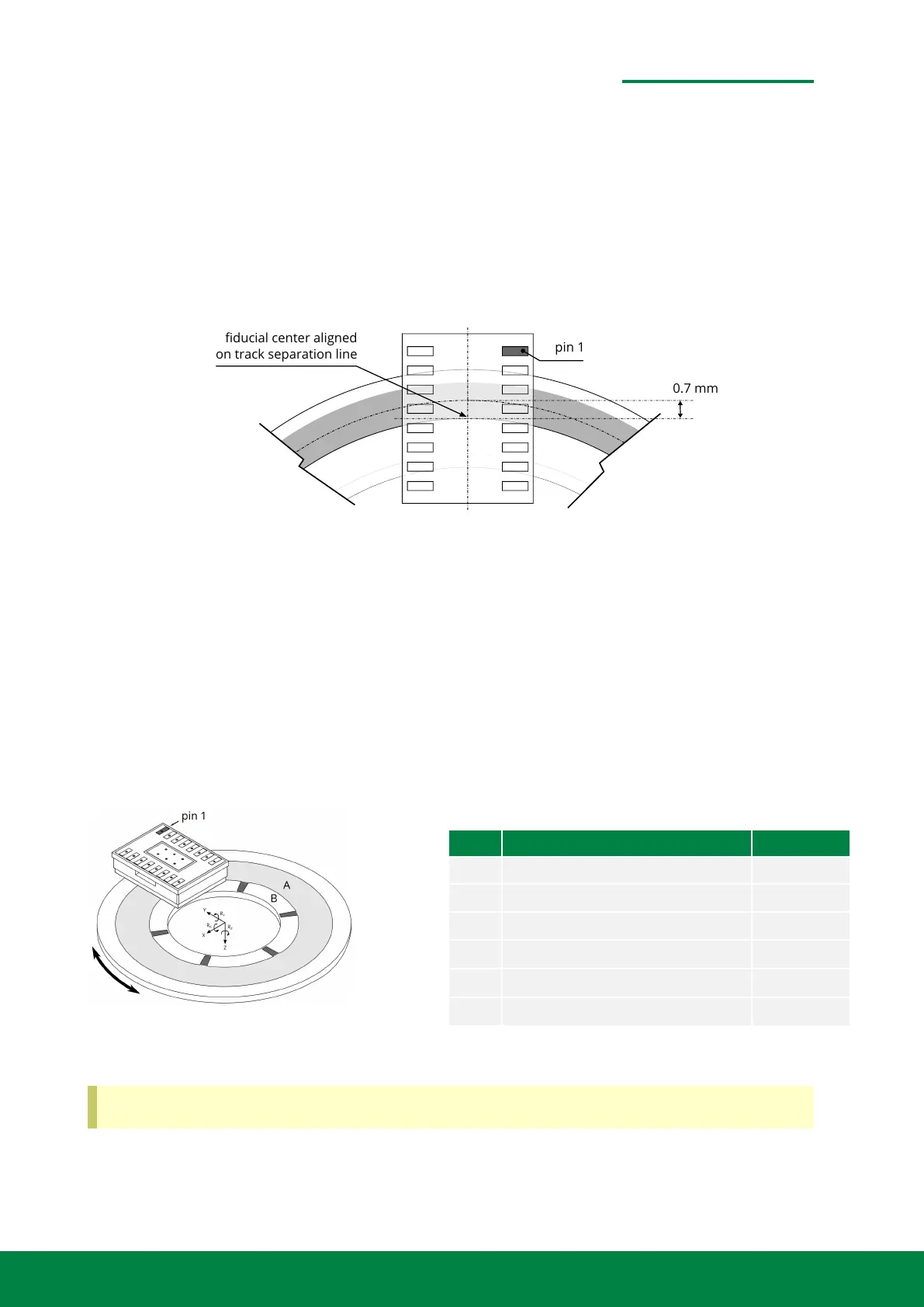
addition, for rotary scales the so called optical centerline (see sect. 4.5.2) has major importance.
The track separation line and the optical centerline need to have a distance of 0.7 mm.
pin 1
fiducial center aligned
on track separation line
0.7 mm
Figure 5.11: Alignment to rotary scales
• Most important for rotary scales is the optical center line OCL.
• The optical centerline and the track separation line should have a distance of 0.7 mm.
• Place the sensor centered to the TSL and centered to a radial line.
• The SmarAct-Logo (Pin 1) should always face the incremental track, which is always the outer
track of the circle.
• The reference track is the inner track of the circle.
Figure 5.12: Tolerances for rotary scales
Axis Nominal Position Tolerance
X 0 mm ±0.05 mm
Y 0.7 mm to the inside from OCL ±0.05 mm
Z 0 mm ±0.15 mm
R
X
0
◦
±1.1
◦
R
Y
0
◦
±2.0
◦
R
Z
0
◦
±1.1
◦
The alignment tolerance is reduced for rotary scales compared to linear scales.
www.smaract.com | Page 52Metirio Encoder User Manual
 Loading...