5 SYSTEM INTEGRATION
5.3.3 Alignment to Goniometer Scales
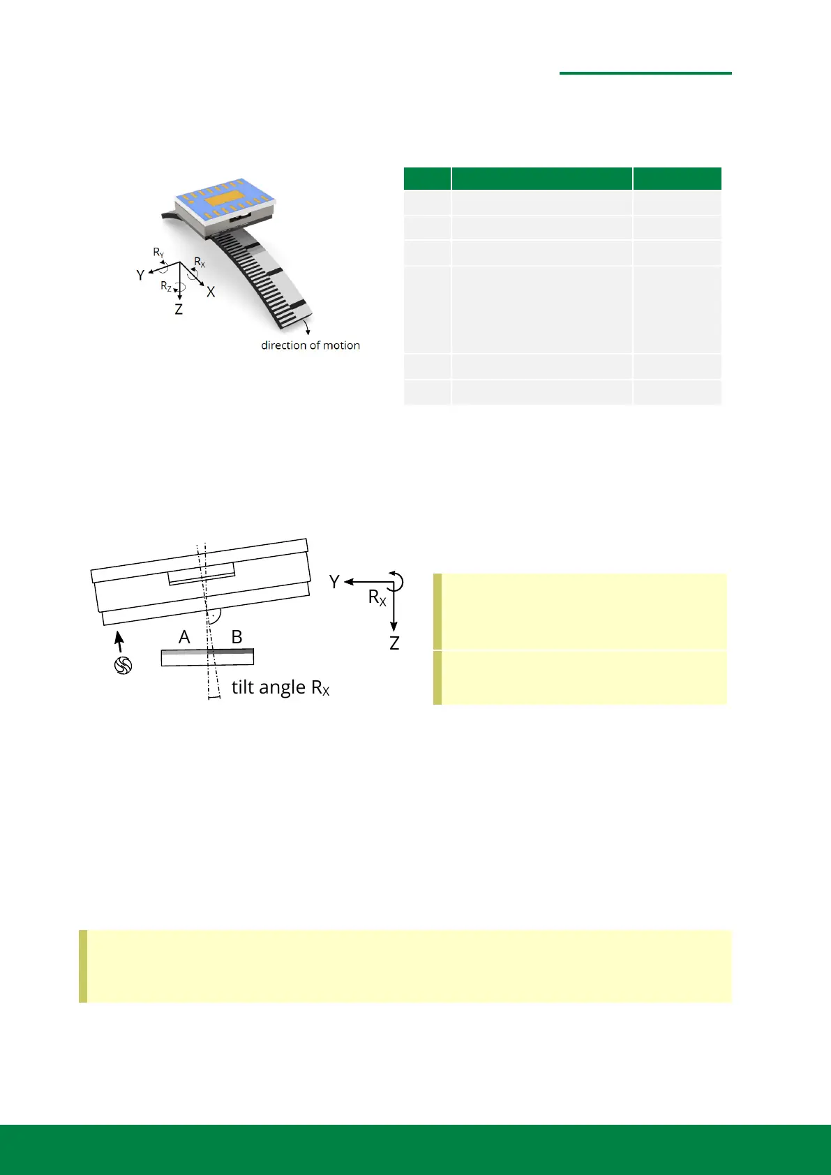
Figure 5.13: Tolerances for Rotary Scales
Axis Nominal Position Tolerance
X 0 mm ±0.05 mm
Y 0 mm ±0.50 mm
Z 0.50 mm (not 1.18) ±0.12 mm
R
X
3.9
◦
(for 70 mm radius)
3.0
◦
(for 90 mm radius)
2.2
◦
(for 100 mm radius)
±0.4
◦
R
Y
0
◦
±1.9
◦
R
Z
0
◦
±0.85
◦
For goniometer scales, the interference pattern will have distorions that lead to signal distortions
of the analog sine and cosine signals. In order to compensate such distoriont, tilting the readhead
around the X-Axis might lead to a round circle with minimized distortion. The tilt angles have been
experimentally verified for three different goniometer bending radii.
Figure 5.14: Tilting the readhead
In order to minimize phase error
a tilted orientation is reccomended,
when using goniometer scales.
The Working Distance is 0.5 mm, in-
stead of 1.18 mm.
• The working distance for goniometer scales is reduced 0.5 mm for convex scales.
• The pivot point of the tilt is the surface of the cover glass at the centerline of the readhead.
• Due to the tilt, the working distance is reduced at the side of the incremental track A.
• The working distance is increased at the side of the reference marks.
• The working distance remains unchanged at the pivot point.
Always tilt into direction of the reference mark (positive R
x
direction). Imagine the readhead
would be a flashlamp to illuminate the scale, then you would tilt the lamp towards the
direction of the reference mark.
www.smaract.com | Page 53Metirio Encoder User Manual
 Loading...