5 SYSTEM INTEGRATION
5.1 METIRIO Readhead Mounting Examples
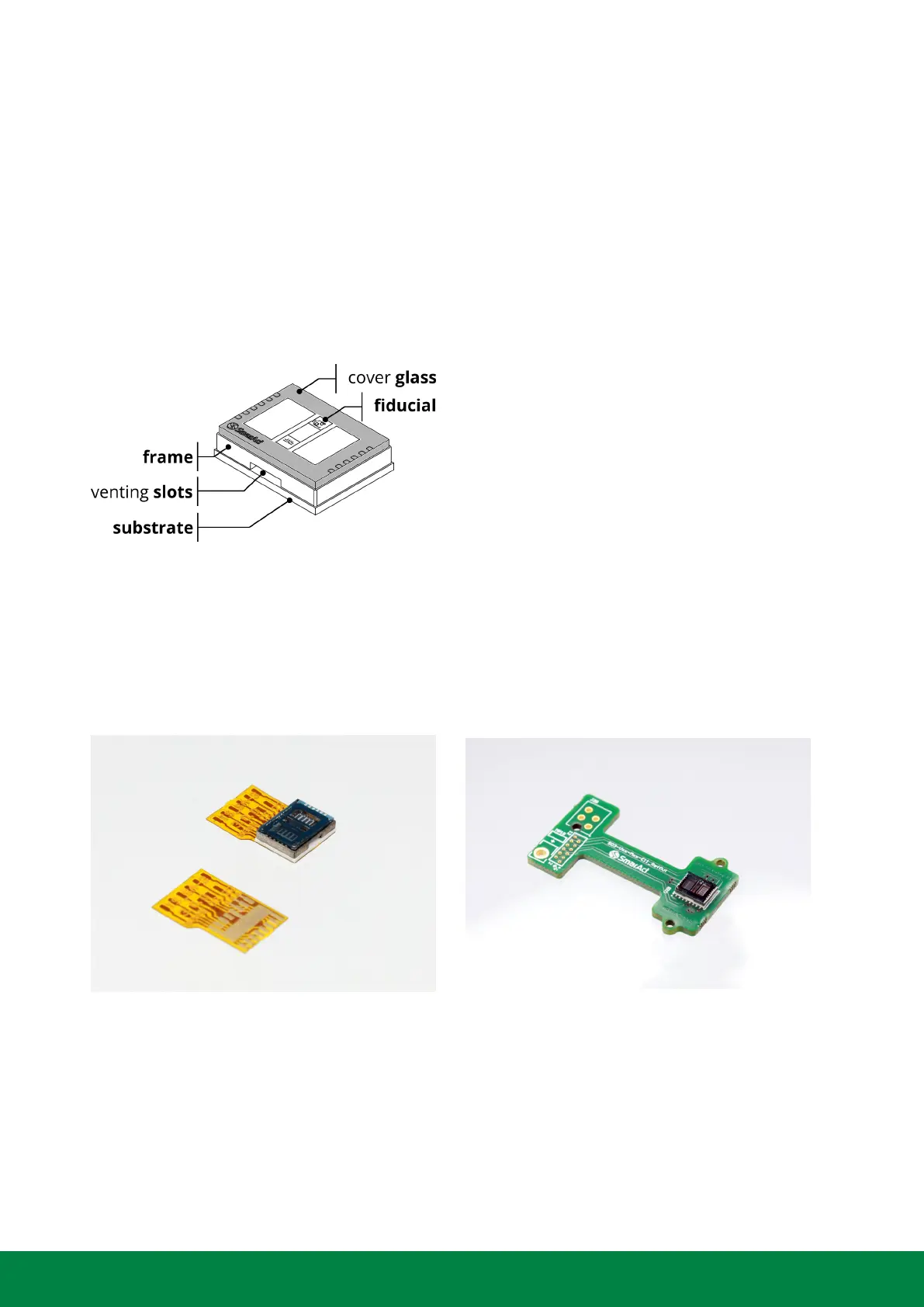
Figure 5.1: Components of the METIRIO Read-
head flip-chip package
The flip chip comprises four main compo-
nents: A substrate, a frame, a cover glass and
the optoelectronics within the package. The
substrate is a ceramic circuit board with sol-
dering pads and a thermal pad on the bot-
tom side. The cover glass contains optically
functional coatings and a fiducial mark. This
mark indicates the centerline which is impor-
tant for the alignment to the scale. The frame
and the cover glass provide accurate reference
surfaces for mounting.
Customized soldering ensures precision and reliability for specific integration requirements. The
METIRIO Readhead flip-chip package can be either glued or soldered. For soldering/gluing, it is
either directly mounted on a PCB and electrically connected to the substrate’s solder pads, or
solder-wired.
Figure 5.2: Examples for soldering of the METIRIO readhead flip-chip package onto PCB.
The readhead can also be connected directly to cabels. In this case the reference surfaces shown
in figure 5.3 should be used for mechanical mounting. The readhead can be attached using adhe-
sives to a mounting edge or mounting frame. The cover glass or the side frame provide the most
accurate reference surfaces. Do not use the ceramic surface as reference.
www.smaract.com | Page 46Metirio Encoder User Manual
 Loading...