4 TECHNICAL DATA
4.2.7 Digital Specification
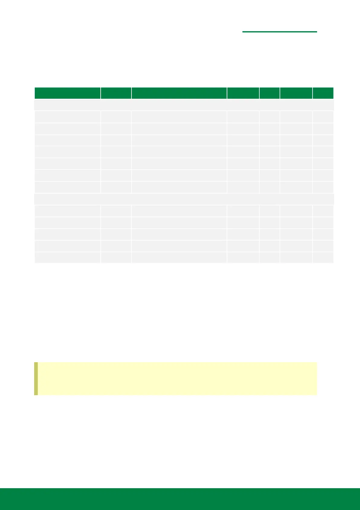
Table 4.8: Digital block
Parameter Symbol Test Conditions / Comments Min. Typ. Max. Unit
Logical Inputs
Input voltage level SLC, SDA, GPI, PD
High V
IH
0.7×V
DD
V
DD
V
Low V
IL
0.3×V
DD
V
Input current level
High I
IH
-10 10 µA
Low I
IL
-10 10 µA
Input capacitance 10 pF
Logical Outputs
Output voltage level GPO 2 mA output current
High V
OH
V
DD
-0.4 V
Low V
OL
0.4 V
Output voltage level SDA at 3 mA sink current
Low V
OL1
V
DD
>2 V 0.4 V
Via it’s digital I
2
C interface the analog signal conditioning blocks of the METIRIO encoder can be
adjusted electrically. Among others, gain settings and settings for the brightness of the light source
can be set. In this section the electrical specification of the digital block is summarized. Further
programming reference and a detailled register description can be found in the user guide UG-
OE00001, which is downloadable on our homepage and available on request.
For users who want to communicate directly with the encoder without programming, SmarAct
provides the ENCODER EVALUATION MODULE in combination with the ENCODER EVALUATION
PROGRAM. These tools make setting up the METIRIO an easy task. However, the following tables
give an overview about the detailed interface specification for any user who needs to communicate
directly with the readhead with his own controller.
A detailed register description for programmers is given in the user guide OE-UG00001
which contains information on how to access, interpret and manipulate the internal mem-
ory. You can download this user guide on our homepage or send a request to our sales.
www.smaract.com | Page 33Metirio Encoder User Manual
 Loading...