5 SYSTEM INTEGRATION
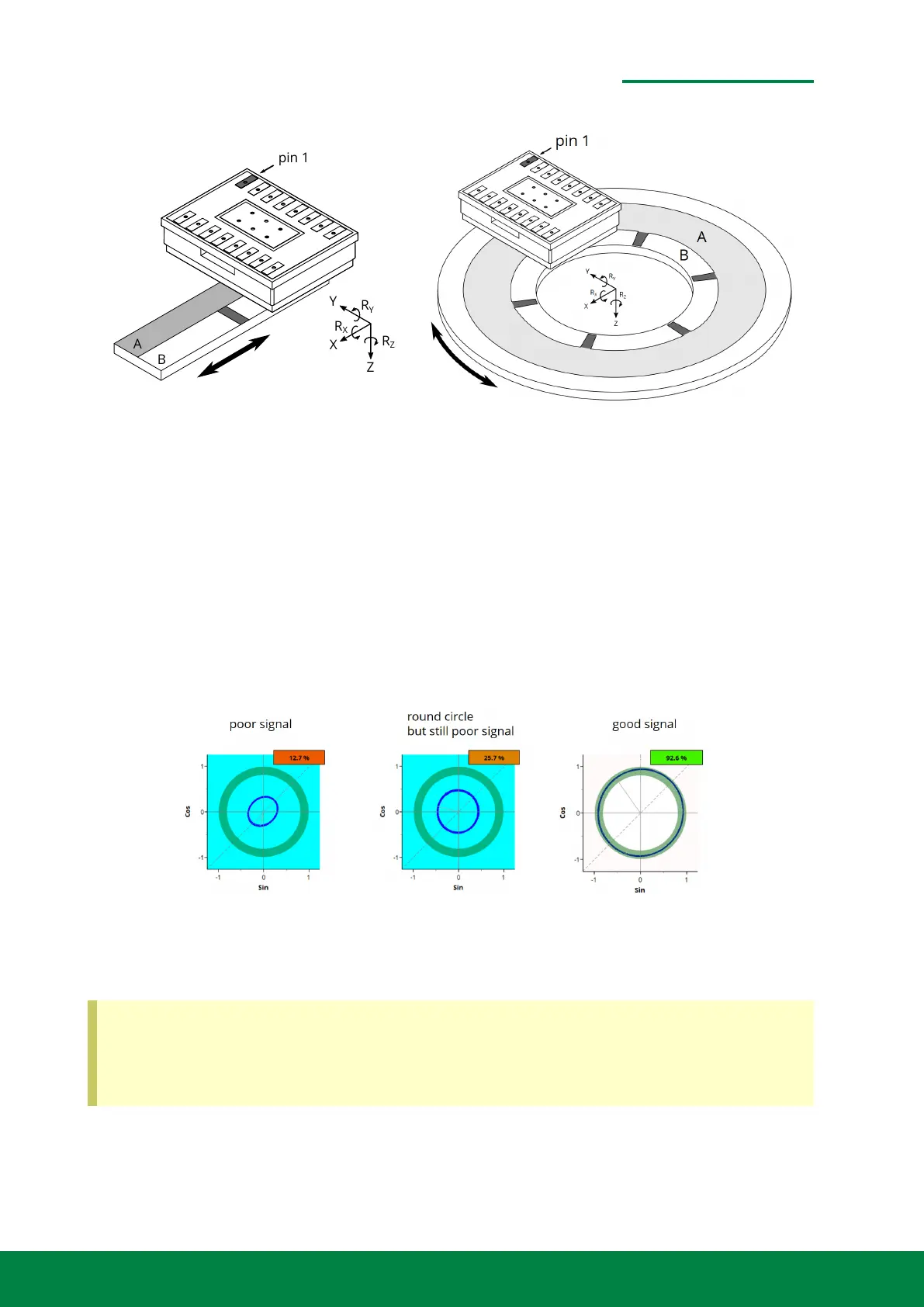
Figure 5.5: General alignment for linear and rotary scales with coordinate system.
The relative position of the readhead needs to stay within given tolerances in order to achieve good
signal quality. Compliance with the tolerances can be ensured by means of mounting devices and
contact edges, whereby the tolerance of the positional relationship between the readhead and the
scale must be ensured in the overall chain of all components. For this purpose utilize the cover
glass surface or the frame surface of the readhead.
If your mounting fixture has adjustable degrees of freedom, the best way to ensure tolerances is
to observe the signals live during alignment. Do not lock the readhead until you have reached
an optimum signal quality. Our ENCODER EVALUATION PROGRAM is best suited for monitoring
signals during active alignment.
Figure 5.6: Monitoring the signal quality with the ENCODER EVALUATION PROGRAM during active
alignment
An optimum signal might only be achieved for proper electronic setting adjustment. The
optomechanical alignment is sufficient, if you achieve a local maximum in signal quality and
a round signal shape. For further instructions refer to our Quick-Start-Guide UG-OE00002,
which is available on request.
www.smaract.com | Page 49Metirio Encoder User Manual
 Loading...