EasyManuals Logo

Smartgen HGM501 User Manual

Smartgen HGM501
17 pages
To Next Page IconTo Next Page
To Previous Page IconTo Previous Page
Page #10 background imageLoading...
Page #10 background image
HGM501 Genset Controller User Manual Page 10 of 17
6. TERMINAL
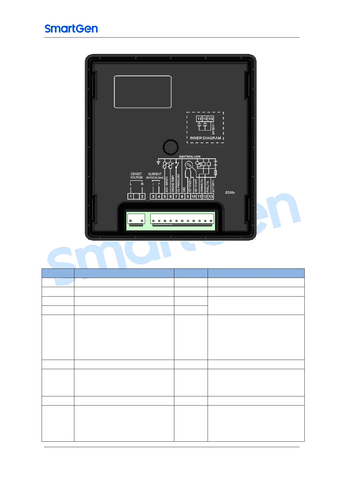
Fig.2 – HGM501 Back Panel
Table 4 -Terminal Connections Description
Terminal
Function
Wire size
Remarks
1
Generator Voltage L
1.0mm
2
2
Generator Voltage N
1.0mm
2
3
Load CT Secondary I (out)
1.0mm
2
Current Transformer Secondary
max current 62.5mA
4
Load CT Secondary I* (in)
1.0mm
2
5
Aux. Input1
1.0mm
2
Can be configured as
programmable digital input
port(active connect to B-);
Also can be configured as
generator temp. sensor.
6
Engine Temperature Sensor Input
1.0mm
2
7
Low Oil Pressure Input
1.0mm
2
Low oil pressure digital or sensor
signal input port; must be
connected to B-
8
Battery Negative Input B-
1.5mm
2
Controller power supply input B-
9
Electric Lock ON Signal Input B+
1.5mm
2
Controller power supply input B+
and fuel relay output (activates
when Electric key is turned to ON
position)

Questions and Answers:

Question and Answer IconNeed help?

Do you have a question about the Smartgen HGM501 and is the answer not in the manual?

Smartgen HGM501 Specifications

General IconGeneral
BrandSmartgen
ModelHGM501
CategoryController
LanguageEnglish

Related product manuals