HGM501 Genset Controller User Manual Page 16 of 17
10. INSTALLATION
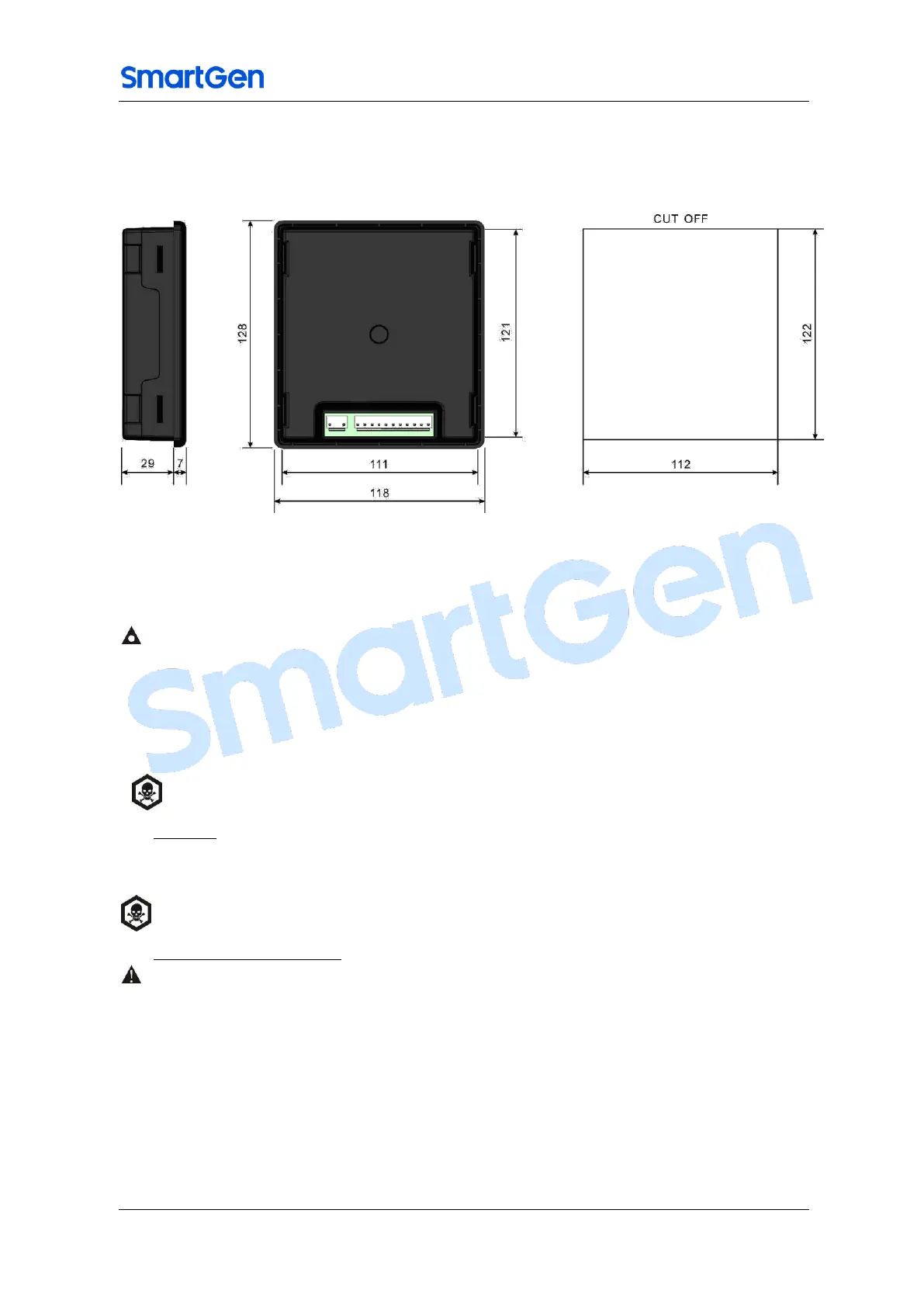
The controller is designed for panel mounting, it is held with the help of fixing clips. Overall
and cutout dimensions can be seen below (unit: mm)
Fig.5 – Overall Dimensions and Panel Cutout
1) Battery Voltage Input
NOTE: HGM501 controller is suitable for 9-18 VDC battery voltage. Battery negative must be reliably
connected to the enclosure of the engine. The controller power supply B+ and B- must be connected to battery
positive and negative, and the wire size must not be less then 1.5mm2. In case of floating charger connect
charger output to battery positive and negative directly, then, connect battery positive and negative poles to
controller positive and negative power supply input port using single lines to prevent charger interference into
normal operation of the controller.
WARNING: When the engine is running, start battery must not be removed.
2) AC input
Current transformer with rated secondary current 62.5mA must be externally connected to
the controller current input.
WARNING! When generator is on-load, C. T. secondary must not be open circuit.
3) Withstanding voltage test
CAUTION: If withstanding voltage test is conducted after the controller has already been installed onto the
control panel, please unplug all controller terminal connections in order to prevent high voltage from
damaging it.

 Loading...