HGM501 Genset Controller User Manual Page 11 of 17
Electric Lock START Input
Hand-turn start, start relay output
(Output activates when electric
lock key is turned to START
position)
Rated current 7A; power supplied
by terminal 13
Rated current 7A; power supplied
by terminal 13
Fuel/Start Relay Common Port
Fused and connected to start
battery positive
NOTE: Controller within the LINK port, which connect to SmartGen’s SG72 adapter. It is can be set or
check genset’s real time data via PC software.
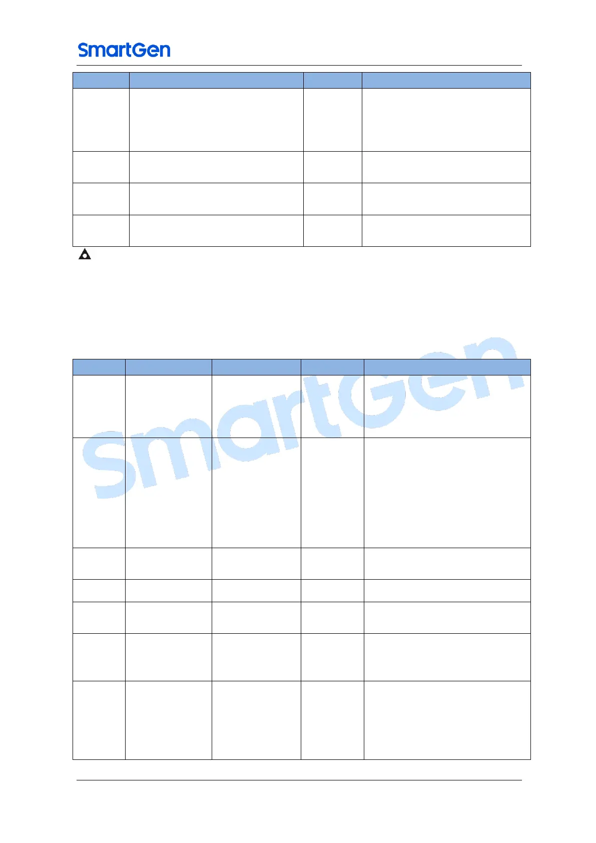
7. CONFIGURABLE PARAMETERS
7.1. CONFIGURABLE PARAMETERS TABLE
Table 5 – Configurable Parameters
1P:1P2W
2P:2P3W
3P:3P4W
4P:Double Rated Volts
110 V
115 V
120 V
130 V
220 V
230 V
240V
Generator rated voltage value
selection
Generator rated frequency
selection
Generator rated Active power
Irrespective of whether gen-set
auto protection is enabled
Unit: A/62.5mA
(Must correspond to the used
current transformer)
Engine
temperature
sensor type
L-0:Not used
L-1:TE1(SGX Sensor)
L-2:TE2(SGD Sensor)
L-3:TE3(PT100 Sensor)
L-4:TE4 (See TE4/TG4 Sensor

 Loading...