MGC120 Petrol Genset Controller User Manual
MGC120 Petrol Genset Controller Version 1.2 2019-02-22 Page 18 of 20
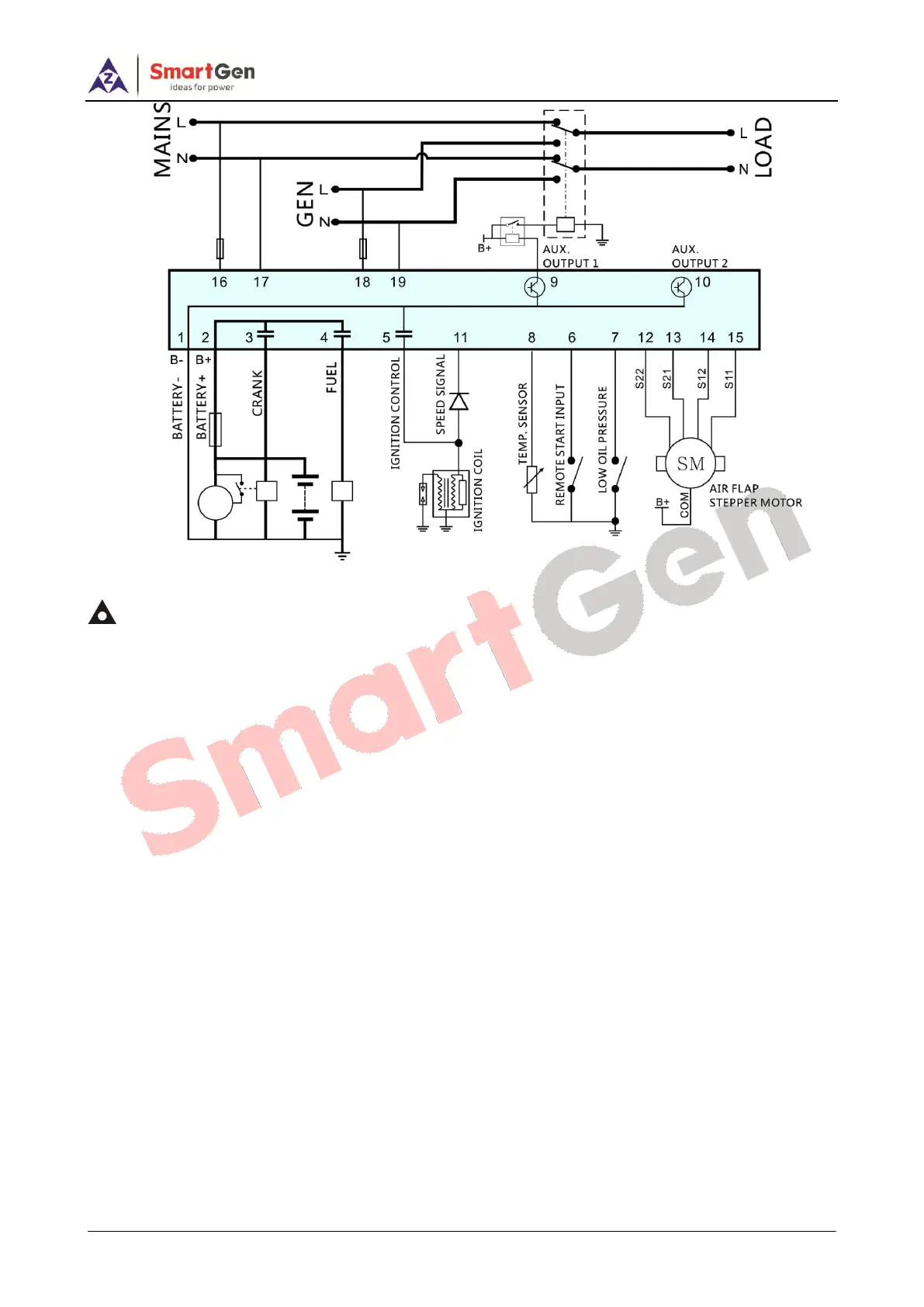
Fig. 6 MGC120 Typical Application Diagram 2
Notes:
1) Programmable output 1 shall be set “Generator Close Output”.
2) S11, S12, S21, S22 shall be connected separately with the stepper motor orange wire, pink wire, yellow wire
and blue wire; stepper motor COM (red wire) shall be connected with battery positive.
3) Terminal 11 must be in series with diode. Diode capacity shall be over 1A and the reverse pressure-standing
value shall be over 1000V.